Continue to Site

Welcome to EDAboard.com

Welcome to our site! EDAboard.com is an international Electronics Discussion Forum focused on EDA software, circuits, schematics, books, theory, papers, asic, pld, 8051, DSP, Network, RF, Analog Design, PCB, Service Manuals... and a whole lot more! To participate you need to register. Registration is free. Click here to register now.

Complementary output - upside down Buck converter

Status
Not open for further replies.

kathmandu

Full Member level 5
Joined
Dec 7, 2015
Messages
298
Helped
7
Reputation
14
Reaction score
7
Trophy points
18
Activity points
3,146
Hello,

I need to build a non-isolated 48VDC to 24VDC (50W) converter. As I don't have much time available for a more advanced topology, I was thinking of the classical buck converter.

I already have some UC3845 (PWM controllers) available so I've decided to use one of them.

The standard buck topology needs a high-side driver (bootstrap or gate transformer) to drive the Mosfet thus I was trying to avoid that.

The usual solution is to use an upside down buck topology (aka "floating buck") to drive the n-channel Mosfet directly. The downside of this circuit is that floating output voltage (referenced to +Vcc).

Well, what if I'll connect the voltage feedback network referenced to ground, like in the schematics bellow?
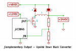
rev-buck.png

I could even use a current sense resistor (ground referenced) for the Mosfet overcurrent protection.

Actually, the "genuine" output voltage will be variable (depending on Vin and the load current) thus keeping the Vin-Vout constant (the intended output voltage referenced to ground).

Is there a problem with a modified topology like this?

- - - Updated - - -

I already found a "bug": the feedback voltage must be inverted (maybe I could use a simple bjt for that).
 

You are correct, the voltage is "floating" with respect to ground. That is the reason you mostly see it on LED drives (which control the output current, not voltage).

I think (although have not tested it) that you could use an optocoupler/TL431 combination, just like you would use on an isolated flyback converter.
It should work...I mean the optocoupler doesn't care where your common mode voltage is, as long as you don't exceed its breakdown voltage...which is VERY high.
 

Is there a problem with a modified topology like this?
Only problem is that it will not work as drawn.

The output of the buck regulator will be across the capacitor C, not between C and ground. This creates a complication with the voltage feedback, because the feedback is with respect to ground, but the buck regulator output is connected to the 48v input, not to ground.

While this achieves a very simple gate drive, it greatly complicates the voltage feedback.
 

After a second look, seems like this circuit it's not going to work at all.

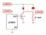
Take a look at this diagram:

rev-buck1.png

The R load must have been in series with the Mosfet switch (and the output inductor) for this circuit to work.

As drawn in the above schematics, the output inductor would never be charged regardless the Mosfet switch state.
 

If you want to do your 50w Buck with uc3845, here is a way to do it...ltspice sim and pdf schem attached.
 

Attachments

  • Buck uc3845.TXT
    10 KB · Views: 79
  • Buck uc3845 _50W.pdf
    21.4 KB · Views: 139
Many thanks, @treez.. but that's way too complex for my needs.

I guess I'll use the floating high-side driver part of the common IR2110(3) chip.

As for UC3845, I'm going to use voltage control only (and I'll put a plain fuse at the input/output for overcurrent protection).

I don't need a very precise voltage regulation, I just need to step down the 48VDC input voltage to "something" around 24VDC.

- - - Updated - - -

BTW, what about the fly-buck topology?

As I need a 12VDC power supply for the Mosfet driver and the UC3845 chip, I wonder if I could use a second winding across the output inductor to get this housekeeping voltage (I'll use a 12VDC linear regulator at startup).
 

I redrew your schematic to show you how the load is wired....its common rail is the positive input.

The feedback is achieved with an optocoupler-zener (or a TL431) arrangement as shown.

IMG_1019.JPG
 
Thank you for your time! Actually, I know how this "upside down" buck converter works but I needed a ground referenced output voltage.

The schematic you have drawn represents the usual "floating" (V+ referenced output) buck topology.

Seems like I can't avoid the high-side Mosfet for a buck topology.

I might have been using a flyback/forward/push-pull converter (for their low-side Mosfets) but I hate the unconstrained (unclamped) topologies (my available Mosfets for this project being 100V rated).
 

If its possible to turn your 48v supply around, here is a buck boost topology I have had some success with.
Buckboost.jpg
The advantages are :
Simple gate drive, simple inductor, fewest components.
Constrained drain flyback voltage.
If the mosfet blows up, the output goes to zero, does not short to 48v
 

Greetings, @warpspeed!

Does your circuit supposed to look like that or there's a mistake in your diagram?

boost-01.png

I have to make myself clear: my 48VDC power supply is ground referenced (-48V connected to ground) and I need to get a 24VDC output voltage referenced to ground (-48V) too.

Regarding your schematic, if I connect the Rload to ground (-48V) as intended, there will be a continuous current flowing from +48V bus through the inductor and Rload to the ground thus it won't work.

I hope there was a mistake in your diagram as I would really like a circuit that simple to work.

Could you try to redraw your circuit please? Does the "ground" sign in your diagram supposed to be tied to +48V or were you refering to a different "ground"?
 

Warpspeed was (on quick look) drawing a standard buck-boost topology which is a good way to meet some of your goals. It converts 48V to 24V with minimal gate drive circuitry. But yes, it inverts.

You've drawn a boost topology. The problem is that it can't prevent current flowing from Vin to Vout, hence why it's only used for boosting.
 
Yes, its a standard buck boost inverting circuit, and the circuit and polarities as drawn are correct.

Your first post did not mention polarity, only reducing 48v to 24v, and sometimes with a floating source such as a transformer/rectifier or solar/wind or a battery, either side of the source can just as easily be grounded.

All things considered, a standard "right way up" buck converter with an isolated gate driver chip such as HCPL3120 would probably be the simplest.

Beware of using bootstrapping to power the isolated gate driver with the buck topology.
It may not be able to start up, and there can be problems if you ever reach extremes of duty cycle. Best to use a small dc/dc isolated power module to provide continuous reliable isolated gate drive power.

I have never like the buck topology, because failure of the switch can easily cause a sometimes catastrophic down stream over voltage.
 
Many thanks for your advices.

I guess I'll stick with the two-switch flyback topology then (clamped, we have discussed it in another thread).

I have already made such a converter recently with very good results but this time I didn't have a spare ferrite e-core available for the flyback coupled inductors (I only had some toroids thus the buck topology idea).

That's it, I'll try to retrieve an e-core from an old circuit to complete my current project. Thank you once again for your kind support.
 

Status
Not open for further replies.

Similar threads

Part and Inventory Search

Welcome to EDABoard.com

Sponsor

Back
Top