Continue to Site

Welcome to EDAboard.com

Welcome to our site! EDAboard.com is an international Electronics Discussion Forum focused on EDA software, circuits, schematics, books, theory, papers, asic, pld, 8051, DSP, Network, RF, Analog Design, PCB, Service Manuals... and a whole lot more! To participate you need to register. Registration is free. Click here to register now.

Filtering frequencies from 0Hz to 20Hz

Status
Not open for further replies.

adrian1232

Junior Member level 1
Joined
Jan 22, 2011
Messages
16
Helped
0
Reputation
0
Reaction score
0
Trophy points
1,281
Activity points
1,446
Hi all,

I need to implement a high-pass filter to eliminate baseline drift to my signal. The wanted frequency range is between 25Hz to 400Hz. I alteady implemented a low-pass filter to remove any unwanted noise above 400Hz.
I need the high-pass filter to have an adjustable gain from 1 to 40 by using a potentiometer.
Are there circuits/ICs to implement the high-pass filter with an order of at least 2?
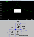
I tried several designs, with the one attached (Multiple Feedback filter) providing the best results. The problem that I am having with this design is the gain. Why is the gain increasing with the input frequency? and what resistor has to be varied to adjust the gain?

Any help would be greatly appreciated.

Capture.JPG
 

. Why is the gain increasing with the input frequency? and what resistor has to be varied to adjust the gain?
View attachment 128439

The gain of a filter is frequency-dependent - and the gain is rising for a highpass.
For the maximum gain you must analyze the circuit for infinite frequecy - as one can see the maximum gain is Amax=-(C3/C2).
 

Thanks for the reply. Is there any similar circuits with a gain not dependent on the frequency?
I tried a 2nd order Sallen Key filter. The problem with the Sallen Key is that I need an offset of 1.5V at the output of the filter. To obtain this I need to apply -1.5V at the negative input of the op-amp. This is not possible to apply for my project since I am using a single supply rail. Is there a way to get around this problem?
 

What is the maximum gain you measured at high frequencies?
It should be a gain of 1.

If you want to vary the gain without affecting the frequency rolloff, then the easiest way is to add another simple inverting or non-inverting op amp gain stage.
Varying the gain of an active filter will affect its corner frequency.
 

A Multiple Feedback Bandpass filter usually has a very narrow bandpass at its single peak frequency then gradual slopes for frequencies away from its peak frequency.
You should use Sallen-Key highpass and lowpass filters. They cannot be fed from a volume control because they should be fed from the low output impedance of an additional opamp that can have a volume control on its input.
 

Attachments

  • MFB filter.png
    MFB filter.png
    19.2 KB · Views: 174

A Multiple Feedback Bandpass filter usually has a very narrow bandpass at its single peak frequency then gradual slopes for frequencies away from its peak frequency.
You should use Sallen-Key highpass and lowpass filters.
Not necessarily a very narrow bandpass. It's a second order bandpass that can be designed with any Q respectively bandwidth of your choice. But I agree with the conclusion. If you want separate high- and low-pass corner frequencies, implement separate filters.
 

Hi again. The low-pass filter is already implemented. The problem is with the high-pass filter. I want the high-pass filter to have adjustable gain with a potentiometer and a fixed output offset of 1.5V. The filter needs to be powered from a single supply rail.
I was testing the Sallen-key attached below. It worked fine but I had to apply -1.5V at Vref to get the 1.5V offset at the output. Is there another method to get the 1.5V offset without introducting any negative voltages?

Capture.JPG
 

Thanks for the reply. Is there any similar circuits with a gain not dependent on the frequency?
It is the main property of a high pass to have gain that is increasing with frequency!
Otherwise, it is not a high pass!
 

But the filter should stop amplifying the signal once the cutoff frequency is reached, no?
 

You can't adjust the gain of the 2nd order Sallen-Key filter in post #7 without changing the cut-off frequency and Q at the same time. Maintaining the bias point with unipolar supply is another problem.

You can make a modified Sallen-Key circuit with low impedance gain setting network and connect the highpass resistor R1 to the OP inverting input instead to the output. But it's much easier to combine a fixed gain filter with separate gain stage.
 
Your resistor values are WAY TOO LOW causing the capacitor values to require an electrolytic type that have poor tolerance and must have the correct polarity.
Your pot affects the response so with the equal RC values the gain must be fixed at about 1.6 times for a Butterworth response. I was told that if the gain is higher than 3 then the filter becomes an oscillator but a simulation does not show oscillation.
 

Attachments

  • sallen-key highpass filter.png
    sallen-key highpass filter.png
    40 KB · Views: 162
Thanks for the replies. So the only way to apply variable gain is to use another op-amp at the output? and for these requirements (i.e. a filter which can attenuate frequencies from 0Hz to 20Hz), which filter design would you recommand? is it the Sallen-Key, the multiple feedback or any other design?
 

You need a highpass filter so the MFB filter is not correct. A Sallen-Key filter can have a sharpness as good as you want by using enough "orders" and if the alignment is Butterworth then its passband is very flat but its corner is fairly sharp. A Sallen-Key filter must be fed from a low impedance so an opamp can be used to feed the filter, and a volume control can feed this opamp. Use a dual opamp IC that is the same size and almost the same cost as a single opamp.
 

You need a highpass filter so the MFB filter is not correct. .

Why should the MFB filter be "not correct"?
Of course, you can use the MFB topology. It is as good as the 2nd-oder Sallen-Key structure, for some properties it is even better (less sensitivity to parts tolerances)..
 

Why should the MFB filter be "not correct"?
Of course, you can use the MFB topology. It is as good as the 2nd-oder Sallen-Key structure, for some properties it is even better (less sensitivity to parts tolerances)..
1) He said he already has a lowpass filter and wants a bandpass from 20Hz to 400Hz which is too wide for a MFB filter.
2) The slopes of a wideband MFB filter are only 6dB/octave which is very poor. But a MFB filter has sharp slopes when it is a narrow band filter which is not wanted here.
 

I suspect a misunderstanding. A high-pass can be implemented in MFB topology as well as a band-pass in Sallen-Key.

As far as I understand, the OP is only asking for the high-pass function because the low-pass already exists.
 

1) He said he already has a lowpass filter and wants a bandpass from 20Hz to 400Hz which is too wide for a MFB filter.
2) The slopes of a wideband MFB filter are only 6dB/octave which is very poor. But a MFB filter has sharp slopes when it is a narrow band filter which is not wanted here.

The slopes of a transfer function do not depend on the filter topolgy - only on the filter order.
 

The slopes of a transfer function do not depend on the filter topolgy - only on the filter order.
The filter order of a MFB filter is only single so the slopes are only 6dB/octave unless the Q is high which makes the bandpass very narrow.

Rod Elliot of Elliot Sound Products also agrees with me, "Note that beyond about 2.5 octaves either side of the resonant peak, the rolloff slope is 6dB / octave. This limits the usable range of the circuit in some respects, as the ultimate slope of 6dB / octave (20dB / decade) is only a first order filter response."

I simulated a MFB filter with a Q about as low as I could get but the bandwidth is still not enough for 20Hz to 400Hz:
 

Attachments

  • multiple feedback bandpass filter.png
    multiple feedback bandpass filter.png
    43.5 KB · Views: 132

The filter order of a MFB filter is only single so the slopes are only 6dB/octave unless the Q is high which makes the bandpass very narrow.

Rod Elliot of Elliot Sound Products also agrees with me, "Note that beyond about 2.5 octaves either side of the resonant peak, the rolloff slope is 6dB / octave. This limits the usable range of the circuit in some respects, as the ultimate slope of 6dB / octave (20dB / decade) is only a first order filter response."

I simulated a MFB filter with a Q about as low as I could get but the bandwidth is still not enough for 20Hz to 400Hz:

Each 2nd-order bandpass has a first-order roll-off on both sides of the center frequency. For large Q-values there is a kind of "peakig" near to the center frequency.
However, there properties are independent on the chosen topology - Sallen-Key or MFB or GIC or...

But - if I am not wrong, the questioner intends to use a 2nd-order lowpass in series with a 2nd-order highpass. In this case, we have a 4th-order bandpass with second-order roll-off properties.
Of course, again to be realized with either topolgy - Sallen-key or MfB or..
 

Status
Not open for further replies.

Similar threads

Part and Inventory Search

Welcome to EDABoard.com

Sponsor

Back
Top