Continue to Site

Welcome to EDAboard.com

Welcome to our site! EDAboard.com is an international Electronics Discussion Forum focused on EDA software, circuits, schematics, books, theory, papers, asic, pld, 8051, DSP, Network, RF, Analog Design, PCB, Service Manuals... and a whole lot more! To participate you need to register. Registration is free. Click here to register now.

Using n-channel mosfet on low side in buck converter???

Status
Not open for further replies.

aamir

Junior Member level 2
Joined
May 30, 2004
Messages
21
Helped
6
Reputation
12
Reaction score
6
Trophy points
1,283
Location
Pakistan
Activity points
257
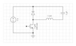
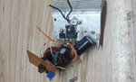
Can we use n-channel mosfet on low side in buck converter instead of high side for simplicity as shown in image because in this case we can directly drive mosfet from pwm ic with minimum losses and heat.if its ok then what should be the inductor value for an output of 12-14 volts 20 amps having switching frequency of 30 khz?thanks in advance to all helping friends.

- - - Updated - - -

Here is the image
 

Attachments

  • IMG-20160415-WA0043.jpg
    IMG-20160415-WA0043.jpg
    36.4 KB · Views: 367

Although your component arrangement will work, it still remains for you to set values to get reasonable performance.

Example, your supply is 1V. It needs to be greater than 14V, if you wish output to be 14V.

Attach a load resistor across the capacitor. Calculate its ohm value so it conducts your specified load of 20 A at 14V.

Try inductor values between 50 uH and 500 uH. You'll need to play with this value until it cooperates with your switching frequency and duty cycle.

Calculate a duty cycle for turning the mosfet on and off. You can expect to make a few adjustments, until output voltage settles at your desired level.
 
Thanks brad.actually i have already built and tested a buck converter on breadboard using Tl494 and Irf1407 with duty cycle 0-100% adjustable.input is variable i.e 16-40 volts and output is 12/14 volts.i provided 24 volts in and adjusted output to 12 volts.with a load of 60 watts on output for 5 mins, fet was totally normal with a very small heat sink.only diode was warming up a little.inductor was 200uh on 15khz freq.toally satisfied with the result but wanted to confirm it from experts.

- - - Updated - - -

One more thing.input was 70 watts and output was 55 watts.whats the efficiency of converter?
 

One more thing.input was 70 watts and output was 55 watts. whats the efficiency of converter?
The way I learned it at school that makes 55/70 = 0.785 (78.5%). Not very good for a switched mode converter.

Usually, a buck inductor will be selected so that current ripple is about 20 to 30% of rated current. Respectively, the converter operation changes to discontinuous mode (DCM) below 10 to 15 % of rated current.
 
  • Like
Reactions: aamir

    aamir

    Points: 2
    Helpful Answer Positive Rating
Agree, 78% is not brilliant, but it is probably pretty typical for a simple 12v 20 amp buck regulator.

There is 70 - 55 = 15 watts of heat going somewhere, spread between the mosfet, diode, core and copper winding. Probably nothing is getting outrageously hot, but still 22% of the power is vanishing, is not a stellar result from the efficiency point of view.

Raising the efficiency, probably means bigger everything, and that may not be either economical or practical.
But it should work reliably as is, and do the job.
 
  • Like
Reactions: aamir

    aamir

    Points: 2
    Helpful Answer Positive Rating
This converter is not properly built on pcb/veroboard yet.i m still testing it.today i made a little change to circuit and tested it again.input was 25.3v x 2.8a=71 watts and output was 12.7v x 5a=63.5 watts so efficiency is 63.5/71=89.4%. I think its not bad.
 

It will be pretty difficult to do any better, especially if the losses are fairly evenly spread around the various power components.

The simple rule is, if one part is getting noticeably hot, then something better may be well worth the trouble. Fix the weak link in the chain.
 

Connsider placing two MOSFETs in parallel.

One Mosfet dissipates 15W
Two Mosfets dissipate only less than half approx.
Because current will be reduced in each and mos ON resistance will be parallel too.
A very big difference.
 

Can you give more details on the inductor/core you are using?
 
  • Like
Reactions: aamir

    aamir

    Points: 2
    Helpful Answer Positive Rating
30 Khz is a low switching speed, by modern standards. The efficiency should be higher.

How are you driving the Mosfet? Proper gate drive improves efficiency tremendously.

Better still, can you provide Drain-voltage waveforms? One showing a single full cycle. Set the ground exactly at a line grid, and adjust the vertical sensitivity to employ as much of the display's vertical resolution as possible.
Then a pair more, with a timebase 10X faster, showing the leading and trailing edges respectively.
 
  • Like
Reactions: aamir

    aamir

    Points: 2
    Helpful Answer Positive Rating
The efficiency problem with 20 amps at only 12v will be mostly conduction losses.
The diode is going to lose half a volt or so no matter what,
That is about four percent gone right there.

As total loss is only about ten percent, maybe two percent in the mosfet and four percent in the choke ?

Now suppose we double up on mosfets,conduction losses there might reduce from one percent to half a percent. Hardly worth the trouble.

Suppose we fitted a monster inductor with double the wire cross section.
Losses drop from four percent to two percent. Again hardly worth the trouble.

Its a lot easier to get from 85% to 90% than to go from 90% to 95%.
The point of diminishing returns comes up pretty fast.
 
  • Like
Reactions: aamir

    aamir

    Points: 2
    Helpful Answer Positive Rating
Note that the low side switch can only be used as long as the input and load common don't need to tied together.
 

Can you give more details on the inductor/core you are using?

Dont know exactly about core material but i think its powdered iron like one shown in image obtained from a pc supply.the winding is bifilar and wire is 15 or 16 swg having inductance of 200uh.

- - - Updated - - -

30 Khz is a low switching speed, by modern standards. The efficiency should be higher.

How are you driving the Mosfet? Proper gate drive improves efficiency tremendously.

Better still, can you provide Drain-voltage waveforms? One showing a single full cycle. Set the ground exactly at a line grid, and adjust the vertical sensitivity to employ as much of the display's vertical resolution as possible.
Then a pair more, with a timebase 10X faster, showing the leading and trailing edges respectively.

Mosfet is being driven directly from Tl494 as shown. sorry havent checked the waveform. i agree 30 khz is low switching speed but its only for testing purpose.

- - - Updated - - -

The efficiency problem with 20 amps at only 12v will be mostly conduction losses.
The diode is going to lose half a volt or so no matter what,
That is about four percent gone right there.

As total loss is only about ten percent, maybe two percent in the mosfet and four percent in the choke ?

Now suppose we double up on mosfets,conduction losses there might reduce from one percent to half a percent. Hardly worth the trouble.

Suppose we fitted a monster inductor with double the wire cross section.
Losses drop from four percent to two percent. Again hardly worth the trouble.

Its a lot easier to get from 85% to 90% than to go from 90% to 95%.
The point of diminishing returns comes up pretty fast.

As the converter is not properly built so this can also be a reason for losses.havent checked it with two mosfets in parallel.gonna check it with two mosfets and 300uh inductor but for this purpose i will have to wind the inductor myself :-( ( not readily avaialble here ).last test was with 12 volts 120 watts load on output and input was 28.5 volts. efficiency was still 90%.

- - - Updated - - -

Note that the low side switch can only be used as long as the input and load common don't need to tied together.

Yes u r right.thats why i chose the low side switching for simplicity.
 

Attachments

  • 20160418_110252.jpg
    20160418_110252.jpg
    846.6 KB · Views: 188
  • 20160418_162125.jpg
    20160418_162125.jpg
    563.5 KB · Views: 194
  • 20160414_140735.jpg
    20160414_140735.jpg
    817.3 KB · Views: 180
  • 20160416_201155.jpg
    20160416_201155.jpg
    822.5 KB · Views: 143

Re; the second photo, your bench lab.

Congratulations on a busy work bench.
I'm serious, I'm not being sarcastic! A cluttered and messy bench lab means that the individual is really working hard. My personal heroes in that respect are two of the greatest analog gurus: Bob Pease and Jim Williams.

I particularly like the charred tip of the red alligator clip. It means that you have had "low-impedance-incident". If you have also burned yourself with the soldering iron, you can be considered a real electronics pro.

Thank u so much for appreciating. Basically i m an electronics technician ( repairing desktop cpu, lcd, power supplies, ups etc ) and power electronics is my favourite. Yes i have burnt myself multiple times with soldering iron even my clothes lol but the worst case was when i was just a hobbyist and accidently stepped bare foot on a big soldering iron left on floor still running. Couldnt place my right foot on floor whole week.

So what u say about mosfet gate drive? Any ideas from u or other members to improve the circuit?
 
Last edited:

Here is some visualization of expected peak currents during start up based on your component values.
 

Attachments

  • start_up.png
    start_up.png
    58.8 KB · Views: 185
  • Like
Reactions: aamir

    aamir

    Points: 2
    Helpful Answer Positive Rating
Any ideas from u or other members to improve the circuit?

There is also the idea of interleaving two or more buck converters. It reduces stress on all components. Current is drawn from your supply as a reduced continual waveform, rather than large Ampere bursts. As it stands you'll have 24A or more going through your inductor. Therefore its saturation spec must be greater than 24A. If this is difficult to achieve then you may want to consider interleaving two or more, each carrying waveforms in the area of 12A.

Also have you confirmed your buck converter can have input 16V and output 14V, at 20A?
 

Here is some visualization of expected peak currents during start up based on your component values.

Thanks a lot for ur help and efforts. What u suggest should i go for higher inductance having at least 30 amps or the one being used is ok. How i will know that core is not being saturated at full load.

- - - Updated - - -

There is also the idea of interleaving two or more buck converters. It reduces stress on all components. Current is drawn from your supply as a reduced continual waveform, rather than large Ampere bursts. As it stands you'll have 24A or more going through your inductor. Therefore its saturation spec must be greater than 24A. If this is difficult to achieve then you may want to consider interleaving two or more, each carrying waveforms in the area of 12A.

Also have you confirmed your buck converter can have input 16V and output 14V, at 20A?


Awesome. Interleaving 2 or more buck converters is a great idea as its common in computer mainboards ( v core of cpu ). If i couldnt arrange or make the required inductor then i'll go for interleaving though it will increase complexity and price.what u suggest for interleaving.lets say i m using 2 converters of 12 amps in parallel driven by same pwm source.will they operate at same time or in phase shift mode.
Is bifilar winding of 15 or 16 swg having inductance of 200uh at 30 khz enough for 30 amps or should i go for more? How do i know that inductor is not saturating?
Yes in one test input was 24 volts and output was set to 12.5 volts having load of 120 watts.one battery got totally down and the input became 14 volts.output was still 12.5 volts. Havent checked it on 20 amps yet.
 

By monitoring the current, you can tell if the core is saturating. The current waveform should be a triangular waveform with dead straight sides.
If the triangles are curved, or the current is obviously spiking upward, you can be pretty sure the core is saturating.

If the wire in the toroid has significant resistance, and running hot, you can add another layer of turns and turn your bifilar winding into a trifilar winding.
Just make absolutely sure that the exact same number of turns are added.

As the core is nowhere near full of copper, you could even make a quadrifilar winding with four sets of turns. None of this changes the inductance or has any effect except reducing the dc resistance of the inductor.

- - - Updated - - -

One experiment you could try, is running it overnight with no load connected and ideally, a forced fifty percent duty cycle.
Any temperature rise in the core will be entirely due to core loss. If the core is getting pretty hot under zero load, then that is an efficiency robbing power loss, and a better core material may be worth thinking about.

If the inductor only runs hot under maximum load, its obviously all resistive copper loss. The core will be fine, it just needs a lot more copper.
 

what u suggest for interleaving.lets say i m using 2 converters of 12 amps in parallel driven by same pwm source.will they operate at same time or in phase shift mode.

Here is a handy control circuit. Two control signals are staggered.

Both duty cycles are adjusted simultaneously by a single voltage reference. 51 to 99 % adjustable duty cycle. You may find this range is suitable to handle your expected supply input, 16 to 40V.


- - - Updated - - -

The pot was dialed from bottom to top. The outputs went from 51% to 99%.

- - - Updated - - -

The initial clock is 40 kHz. The flip flop divides by 2. Therefore outputs are 20 kHz.
 
Status
Not open for further replies.

Similar threads

Part and Inventory Search

Welcome to EDABoard.com

Sponsor

Back
Top