Continue to Site

Welcome to EDAboard.com

Welcome to our site! EDAboard.com is an international Electronics Discussion Forum focused on EDA software, circuits, schematics, books, theory, papers, asic, pld, 8051, DSP, Network, RF, Analog Design, PCB, Service Manuals... and a whole lot more! To participate you need to register. Registration is free. Click here to register now.

DC motor drive topology selection

Status
Not open for further replies.

francis29

Member level 5
Joined
Mar 22, 2016
Messages
90
Helped
2
Reputation
4
Reaction score
3
Trophy points
8
Location
India
Activity points
721
I want to drive a PMDC motr. I only want to drive in one direction only.
motor specifications 2HP 120v 14A
Input 120V DC
what topology should i choose?
 

Hi,

Why not using a simple relay?

Klaus
 

Actually i am connecting it to a solar pv array having mpp at 120v and 12A. .so i want to limit current othewise panel voltage drops drastically.
 

One useful tactic is to put an LC filter at the supply input. Then you draw steady current from the PV panels.

A buck converter is a reasonable choice for reducing current to the motor. Make the duty cycle adjustable via potentiometer, since you're not certain what combination of voltage/ current the motor draws.


I want to drive a PMDC motr. I only want to drive in one direction only.
motor specifications 2HP 120v 14A
Input 120V DC
what topology should i choose?
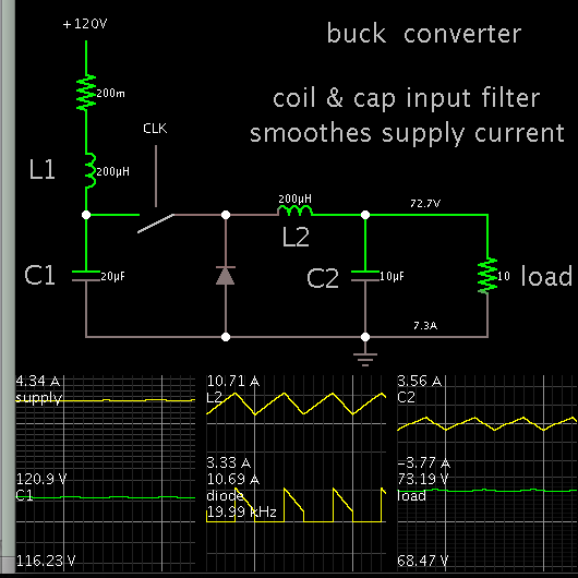
If your MPPT point is 120v, as it would be with four 24v panels in series, or eight 12v panels in series, you only need to reduce the voltage, so Brad's suggestion of a buck topology will be the simplest and easiest to implement.

As Brad says, the input to the buck regulator will be a highly pulsing current, so you will need a pretty large reservoir capacitance directly at the solar panel voltage to feed the buck regulator.

Now you will need two control loops to control duty cycle.
The first will be your MPPT control loop that rapidly reduces duty cycle if the input voltage tries to fall below 120v due to overloading the panels.

The second control loop sets the motor voltage to control motor speed.
This will provide fairly constant rpm, provided there is more solar power available than required by motor load.

So you get constant speed up to the MPPT point, then motor voltage and motor speed falls off, but solar panel voltage cannot be pulled below 120v.
Even though the motor slows, you are still putting max available power from the panels into the motor.

I have a system like this myself operating right now. But its not driving a motor, but an ac mains inverter directly (without any battery).
It gives a constant solid well regulated 240v ac 50 Hz, right up to the MPPT point.
 
But if we are using chopper, motor will be working on voltage less than 120v. so motor can't deliver full output right?
 

Hi,

The MPPT point is only true for the "nominal" ammount of sunlight.
It will change with the ammount of sunlight.

The same time the produced electrical power will change.
With dim sunlight you get less electrical power and thus you can not give full energy (voltage, current) to your motor.

Klaus
 
The MPPT point is only true for the "nominal" ammount of sunlight.
It will change with the ammount of sunlight.

This is not so.

What happens is the panel is a current source, and the current varies between zero to a maximum, depending on available light level, but the peak power output always occurs around the same voltage.

This can easily be demonstrated with a power meter and an adjustable load resistance.

The power output always peaks around the same voltage.
It may only be milliamps in pre dawn twilight, or multiple amps at mid day, but the peak is always at the same solar panel voltage.
Now this peak is really a cusp, and several volts either side of 120v does not make a huge difference, but beyond that it falls over pretty quickly either way.

Temperature will have a slight effect too, but its not too dramatic.

So basically you can build a complex software driven power maximum seeking circuit that rocks the pwm back and forth and get perhaps 99% of what is theoretically possible.

Or you can just build a hardware feed forward system to prevent overloading the panels and get maybe 95%+ of what is theoretically possible, with a vastly simpler control system.

This is not armchair theory, I have such a system built and running right now.
 
Hi,

MPPT = Maximum Power Point Tracking

So indeed we are talking about MPP = Maximum Power Point. Do you agree?
"T" is the tracking, it is the method to find MPP.

***

The MPPT point is only true for the "nominal" ammount of sunlight.
It will change with the ammount of sunlight.
This is not so.
P = power...
Are you saying P is not changing with the ammount of sunlight?

I´d say U, I and P are changing.

(In further you mainly talk about "voltage" instead of "power")
Indeed U is the one value that doesn´t change that much..
So some regulators just work with a constant voltage. But - in my eyes - this is not true MPPT.

I`m referring to wikipedia´s article about MPPT, where it also discusses the "constant voltage" method. But also here they regulate to a voltage depending on "no load voltage" of the solar panel.
https://en.wikipedia.org/wiki/Maximum_power_point_tracking

***
Back to the thread:

Maybe I´m wrong, but to me it seems the OP wants to drive the motor with constant voltage (resulting in constant current and constant power, as long there is no change at the mechanical side)
independent of ammount of sunlight. This is not possible.

In my eyes the regulator needs to lower the motor voltage in times with low sunlight.
The regulator´s output power will always be less than it´s input power.
(And with a motor you can not keep voltage constant and drop current only. It needs to be: Less sunlight --> Less motor voltage --> less motor RPM --> less motor current --> less motor power)

Klaus
 
  • Like
Reactions: francis29

    V

    Points: 2
    Helpful Answer Positive Rating

    francis29

    Points: 2
    Helpful Answer Positive Rating
Klaus, of course power changes with illumination.
But the maximum power point stays pretty much at the same voltage right down to twilight conditions.

Maybe constant voltage is not true MPPT in your eyes, but it comes damned close if you care to do some actual testing yourself.

The way my system works, before sunrise the solar voltage begins to rise up above zero.
But because it is still well below my MPPT set point voltage, the controller stays at zero duty cycle placing no load at all on the panels.

As soon as the voltage reaches the MPPT set point, the controller starts to load the panels, almost like a shunt regulator, drawing whatever current is available. Maybe just a very few mA to start with.

The output from the controller is still pitifully weak and unusable at that point.
As the sun rises above the horizon, we start to see some real power being developed.

If the load is light, the output of the controller goes into its regulated constant output voltage mode, and the solar panel voltage is able to rise well above the MPPT voltage, as the output loading is light.

As you further increase the controller output load, solar voltage falls, but the load voltage stays regulated.

More load still, and solar panel output falls further down to the MPPT voltage, the controller output is still in regulation.

Further (over) loading will cause the controller output to fall (it drops out of regulation) but solar panel voltage cannot be pulled lower than the MPPT set point, where maximum power is still transferred into the load. Even though the output voltage has fallen, the load is still receiving everything the solar panel can provide.

I am using a controller like this to directly drive a 240v 50Hz mains inverter without any battery. Provided there is enough solar available, the output voltage regulation of the inverter is excellent.

For it to work you need enough panels to provide sufficient power under the worst cloudy conditions. But then a software tracker also needs sufficient input power to work too.

I am not making this up. The power for my keyboard right now is coming from just such a controller.
 

But if we are using chopper, motor will be working on voltage less than 120v. so motor can't deliver full output right?

Not quite so; almost full power can be delivered at lower voltage, higher current and slower speed.

Most motors have higher losses at higher currents and therefore low speeds are somewhat less efficient. High speed results in slightly greater power. PM motors have power-vs-voltage curves almost flat.

All depends on the nature of the load. The power transfer from the motor to the load is also critical.
 

Okey i am kind of getting the idea of MPP:)
so current is the problem right?
If i draw more current from the panel at a particular irradiance ie above Imp the panel voltage drops drastically. Right?
so our idea is to limit the current below the Imp. That is why we are adjusting the duty cycle of chopper.
so basically we controlling the voltage to the motor so current also controlled.
right?
One doubt is that motor voltage and current has a linear relationship or not?
 

Naturally you still need sufficient solar panels to do the job.

If you need say 1Kw for your deep well pump motor, you will need 1Kw minimum from the panels under the worst cloudy winter conditions.

That may require 12Kw of installed panels !
The problem is then preventing over voltage to the motor under perfect mid summer blue sky conditions.

I cannot understand why people are so fixated on this software tracking MPPT thing.

A very simple system that always loads the panels down to a fixed minimum voltage under the worst overload conditions will be within a very few percent of the most sophisticated software power trackers available.

If you feel you absolutely must have those very few final extra watts, why not just fit one more solar panel to the whole array and be done ?

- - - Updated - - -

Okey i am kind of getting the idea of MPP:)
so current is the problem right?
If i draw more current from the panel at a particular irradiance ie above Imp the panel voltage drops drastically. Right?
so our idea is to limit the current below the Imp. That is why we are adjusting the duty cycle of chopper.
so basically we controlling the voltage to the motor so current also controlled.
right?
One doubt is that motor voltage and current has a linear relationship or not?
We both posted simultaneously.

MPP is only appropriate where the total electrical load is heavier than the panels can support. As you say, you don't want to overload the panels and pull the voltage right down to the point where power is rapidly decreasing.

If you have excess solar power, then its just a case of regulating the motor voltage so the motor is not going to over speed or overheat.

The panels will always be in overload around sunrise and sunset, no matter how many panels you have. And that is where the MPP part starts to work.
In the middle of the day there should be excess power available.
 

Okey, the doubt still exists :)
we are controlling current to motor by
controlling the voltage to the motor
right or wrong?
 

As this is a PM dc motor, a lot depends on the type of mechanical load on the motor. Current will be roughly proportional to the torque delivered to the load.

If the load toque is fairly constant over the whole speed range, the current will be pretty constant too. Both speed and power will increase with voltage, but the current probably will not vary much.

If load torque rapidly rises with motor speed, current will rise with speed as well.

So not knowing what is being driven, its difficult to say how it will behave.
 

Constant load torque should produce a pretty constant motor current.
It will just turn faster and generate more horsepower with a higher applied voltage.

An example of something like that might be a winch motor, hauling with a constant load tension. Or a positive displacement pump, pumping against a constant head pressure.
 

Status
Not open for further replies.

Similar threads

Part and Inventory Search

Welcome to EDABoard.com

Sponsor

Back
Top