Continue to Site

Welcome to EDAboard.com

Welcome to our site! EDAboard.com is an international Electronics Discussion Forum focused on EDA software, circuits, schematics, books, theory, papers, asic, pld, 8051, DSP, Network, RF, Analog Design, PCB, Service Manuals... and a whole lot more! To participate you need to register. Registration is free. Click here to register now.

Optocoupler Board output error

Status
Not open for further replies.

sabu31

Advanced Member level 1
Joined
Jan 28, 2011
Messages
446
Helped
12
Reputation
24
Reaction score
13
Trophy points
1,298
Activity points
5,153
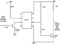
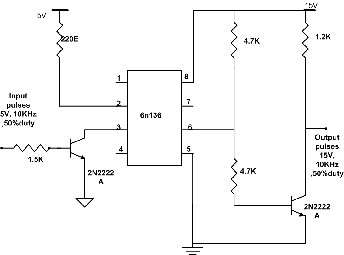
I have an optocoupler board as shown in figure . Though the circuit is working fine in simulation. I actual hardware theres is some wiring error which unable to debug. I am finding that the output is having pulses of peak 7.5V instead of 15V. When no pulses are given to the board, the ouput is 7.5V. What could be the reason. Thanking you.


Maybe someone wired something wrong on the the output side of the opto? Wired as shown will give the results you describe.
 

Attachments

  • opto.png
    opto.png
    15.7 KB · Views: 52

Is it possible to know by simulation that what type of connection would cause the error i mentioned in the first post.?
 

With no pulses the output should be near zero volts.
What is the base-emitter voltage of the right transistor with no input?
 

The output Transistor was damaged i think, as the system worked when i replaced it. Thanks all.
 

Hi all,

For the same optcoupler board , with same input. I am getting following outputs as shown in figure


When i changed the output transistor , there is variation in the overlap. I have two questions


a) Whether it is possible for two working transistors to give overlaps of this nature. The overlap is in range of 2us. The other circuit components remaining same.
b) The signals are to be given to diagonal switches or an H-Bridge inverter, which is modulated in bipolar modulation. What will such type of signal cause in output of inverter, as ideally both signals should be same.
 

For driving a bridge you don't want overlap, you want just he opposite.
You want time between the signals so the the one pair of transistors has time to turn off before the other pair turns on.
 

For driving a bridge you don't want overlap, you want just he opposite.
You want time between the signals so the the one pair of transistors has time to turn off before the other pair turns on.

Hi,

The pulses I am showing is for two diagonal switches of H-Bridge which should of same width and on at same time.
What I want to know is the effect of one of switches being on for more time than the other diagonal switches. Please note that pulses in the same leg are maintained as complementary with a small deadband.

The second thing I want to know is why is the Transistor 2n2222A of different companies giving difference in widths. Thanking you.
 

Status
Not open for further replies.

Part and Inventory Search

Welcome to EDABoard.com

Sponsor

Back
Top