Continue to Site
Follow along with the video below to see how to install our site as a web app on your home screen.
Note: This feature may not be available in some browsers.
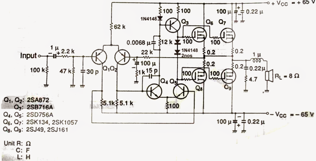
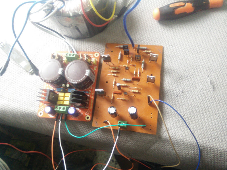
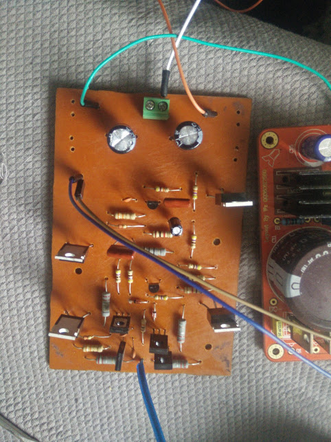
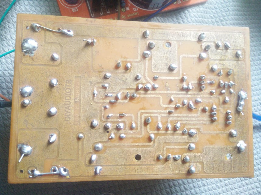
I do not know why all the grounds are not connected together.I have a big problem with Q11 base current , where does it come from?
Frank
so your saying I need a preamp stage to actually hear anything out of the amp? (Line level input) what do you mean by that.