Continue to Site

Welcome to EDAboard.com

Welcome to our site! EDAboard.com is an international Electronics Discussion Forum focused on EDA software, circuits, schematics, books, theory, papers, asic, pld, 8051, DSP, Network, RF, Analog Design, PCB, Service Manuals... and a whole lot more! To participate you need to register. Registration is free. Click here to register now.

Troubleshooting a switch mode power unit (was previously working)

Status
Not open for further replies.

Randomkid199

Newbie level 3
Joined
Apr 12, 2016
Messages
4
Helped
0
Reputation
0
Reaction score
0
Trophy points
1
Activity points
47
Hey All,

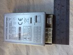
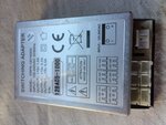
I have 4 lasers with the same problem, The switch mode power supply has stopped functioning properly. They do power on but they only flash/pulse intermittently.

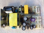
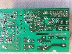
I have run the cause down to the switch mode power unit by A: switching them out between each other(the lasers are pretty much the same model) B: taking them to a 'specialist' who basicly told me they were broken... And C: fault finding with my limited knowledge.

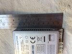
I have used a multi meter across the outputs of the unit and the Voltage is slowly rising then dropping back down to a point that it can't sustain the required power output for the laser unit. I can also hear a fain ticking from the Switch mode power unit when it is plugged in, and the ticking is in time with the light output.

Any help would be greatly received as I am at a loose end.

Thanks In advance

Tim
 

Attachments

  • image1.JPG
    image1.JPG
    584.8 KB · Views: 111
  • image2.JPG
    image2.JPG
    618.2 KB · Views: 93
  • image3.JPG
    image3.JPG
    612.3 KB · Views: 111
  • image4.JPG
    image4.JPG
    697.7 KB · Views: 90
  • IMG_3591.JPG
    IMG_3591.JPG
    550.8 KB · Views: 125

Laser units are often powered by smps acting in "capacitor discharge unit" (CDU) mode....in other words, they are meant to turn on and off. -Its cheaper than making an smps that can drive the full power, because full power is not needed continuously with eg laser diode stacks....they only have to pulse at low duty.

If you want to test the smps, provide the datasheet of it....we can see what is the expected vout and pout, you can then load it with a resistor of that same thing, and see if it works...but you need to assess if its meant to operate in CDU mode or not.

Also check you are using it with proper vin. But really we need the datasheet of the PSU. then the schem of the laser diodes.

- - - Updated - - -

maybe the laser diodes are overloading it.
 

Thanks for the Reply Treez, I was just wondering what data-sheets you needed? I can't seem to find the circuit board scem's online anywhere, the laser draw can be found here though:


(its at the very bottom. I have the unit in front of me so can provide you with any other info you might need! :)
If I wanted to test the 'smps' what would I be looking for?

Thanks Again
 

OK thanks, I can see a smps unit in your top post, then in your post#3 I can see a “kam” unit. Are you saying that the SMPS of the top post is what you found inside the kam unit.?

Anyway, at this point I do not know what load you are trying to drive with the smps unit of the top post. That info is needed, so we can see if you are overloading it or not.

The smps unit of the top post has one 12v,1.5a output and a +/-15v,0.5a outputs.
The 12v one is likely the regulated one, or at least, the most regulated one…….

So if you want to test that smps of the top post……then switch it on first with no load and tell us what voltages you get at the outputs.

Then load the 12V rail with a 12V/1.5A = 8 OHMS resistor (rated for 18w), and again tell us what readings you get on the rails.
Then load the plus and minus 15v rails with 15v/0.5A = 30 ohm resistors (each rated 7.5w) and again tell us what output voltages you get.

Preferably look at the output voltages with a scope over multiple time bases so you can see what its doing dynamically.

- - - Updated - - -

Make sure you have removed all other loads off the outputs for these tests.

- - - Updated - - -

It sounds to me like you are trying to drive laser diodes (?)........and this is worrying because they need a current regulated smps to drive them with, and the smps you showed in the top post is a voltage regulated one....though maybe there is a current regulator between them(?), i dont know.
 
If the SMPS is defective you don't need to care about the laser circuit details. Testing the power supply with load resistors as previously suggested should clarify things.

The other possibility is that there's a short in the laser driver circuit part.
 
Thanks guys, Just to clarify, the Voltage is raising then dropping across all the outputs, I don't have any load resistors at the moment but when I get them, what would I be looking for on the multimeter? also as it is happening across all the outputs wouldn't it be something that all the outputs share like an IC chip?

I have searched for most of the parts that I think the outputs are sharing and there is only one part that I have noticed that looks like they all share, it's an IC chip with '81202 8178 G' which looks like a 4 pin IC chip, however I can't find the exact part, Although I have found this: https://elcodis.com/parts/5701458/PC817B_p3.html#datasheet which looks the same and would have the same function? could a faulty IC chip like this cause this problem?

Could one blown resistor or capacitor cause this problem across all the outputs?

Thanks!

Tim
 
Last edited:

that's the feedback optocoupler.
It sounds to me like you are overloading the power supply, perhaps due to a damaged or wrong load, but until you can do the resistor test, or actually tell us what load you are loading it with, not much can be said.

Meantime though, you could put it on no load and see what happens.....or even just whatever known load you have available (as long as it doesnt overload it).

Look to see what vout you get, and on the scope check its a flat line and not dancing about.
 

Thanks for the reply Treez,

the power output is fluctuating with no load across all 6 outputs, so I don't think its a power draw overload as it would be a steady power output with no load right? I have ordered the load resistors but they will take a few days to arrive. It seems to me that it's not switching on and off fast enough to keep the power constant, what component would I be looking for on the circuit board that would be operating this?

Many thanks again!
 

Status
Not open for further replies.

Similar threads

Part and Inventory Search

Welcome to EDABoard.com

Sponsor

Back
Top