Continue to Site

Welcome to EDAboard.com

Welcome to our site! EDAboard.com is an international Electronics Discussion Forum focused on EDA software, circuits, schematics, books, theory, papers, asic, pld, 8051, DSP, Network, RF, Analog Design, PCB, Service Manuals... and a whole lot more! To participate you need to register. Registration is free. Click here to register now.

Inductor & capacitor design for automatic voltage regulator

Status
Not open for further replies.

anoop kr

Member level 4
Joined
Aug 6, 2010
Messages
69
Helped
0
Reputation
0
Reaction score
0
Trophy points
1,286
Location
kerala
Activity points
1,885
Hi All
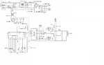
I am designing an Automatic Voltage Regulator(AVR). The Specification of the device is
1). Input Voltage:- 230v AC,50Hz
2). Output Voltage:- 6V-70V DC, 4A
3). Converter:- PWM Using KA3525
4). Output Mosfet Driver:- IR2110
5). Topology Used:- Half Bridge(Using IRF840)

I am so much worried about the lowpass filter design using capacitor and the inductor. I put some values of capacitor and inductor but at that time the mosfets were burned out. I used some softrware for the inductor design but in vain. The Software i used is "MICROMETALS "DESIGN OF INDUCTORS FOR POWER FILTER APPLICATIONS".

I am uploading the circuit diagram also. Somebody please help me:-(
 

Attachments

  • sg3525-shutdown-current-sens-circuit.png
    sg3525-shutdown-current-sens-circuit.png
    49.7 KB · Views: 125

Hi,

your load seems to be an inductive load.
But the output voltage seems to be DC.. or at least carries a lot of DC. Therefore the load current will be dominated by the DC current. This is U_out / R_DC.
R_DC may be very low and thus the current may be very high. Maybe too high.

Klaus
 

Re: Inductor & capacitor design for automatic voltage regulator

yes of course. so how can i calculate the inductor and capacitor values.

- - - Updated - - -

is there any specific formula for calculating the inductor and capacitor values??
 

Hi,

what do you want to achieve?
* reduce EMI?
* generate a clean DC voltage with specified ripple voltage?

For clean DC you need to know: switching frequency, output impedance (or load impedance) at switching frequency, expected ripple voltage.


Klaus
 

Your circuit looks like a parallel resonant converter without the secondary.
Also, i do not see any primary current sensing.

Your circuit also reminds me of a fluorescent ballast driver, but where the fluorescent tube would be, you have an inductor. But then again your controller is fixed frequency , and some variability of switching frequency is best for the above two mentioned converters.
 

i just want to know how to get the exact values of the output inductor(L) and the capacitor(C) for the specified output requirements. Is it possible to replace the output inductor(L) and the capacitor(C) with a fast switching high power diode and a capacitor??. i saw one real circuit like that. Thats why i asked. The inductive load resistance is about 100ohms.
 

ok but your circuit doesnt show a secondary for the half bridge. As it stands you would have an AC current in your "load".
 

Status
Not open for further replies.

Similar threads

Part and Inventory Search

Welcome to EDABoard.com

Sponsor

Back
Top