Continue to Site

Welcome to EDAboard.com

Welcome to our site! EDAboard.com is an international Electronics Discussion Forum focused on EDA software, circuits, schematics, books, theory, papers, asic, pld, 8051, DSP, Network, RF, Analog Design, PCB, Service Manuals... and a whole lot more! To participate you need to register. Registration is free. Click here to register now.

CD4007 experiment to build a push pull

Status
Not open for further replies.

luca89

Junior Member level 1
Joined
Feb 29, 2016
Messages
16
Helped
0
Reputation
0
Reaction score
0
Trophy points
1
Activity points
136
Hi everyone, I would like someone of you give a suggestion about the problem i have to build an electronic circuit.

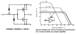
(1)I want to build aPUSH-PULL amplifier (which is not THE LOGIC INVERTER but is an amplifier) made in CMOS by using the CD4007ub
(2)I made the following connection to try :

norm_circ.PNG

and it work. But the system start to heat up if i connect 14 (bulk of pmos) to the 12 (output) and Vin is 0V . Why?

norm_circ.PNG

I wanted to connect the 14 to 12 because i wanted to eliminate the bulk effect of the PMOS => VSB=0

Anyone know what happen? Thank you very much . Have a nice day
 

Hi,

Hot means power dissipation.
Power dissipation means current.

The device is specified for some mA of output current.
If you ensure that the current is within these some mA then the temperature rise should be low. Not hot.

Therefore I assume the output current is too high.

Other possibilities:
* floating inputs
* high frequency
* too much supply voltage
* internal isolation destroyed by an ESD pulse

Klaus
 

Of course in CMOS you can exchange source and drain, so pin 12 can be your common source output (symmetrical source follower), your new NMOS drain connection (pin 9) has to be connected to the pos. power supply pin 14 (its parasitic diodes D1 are already internally connected to the neg. power supply pin 7) , and the new PMOS drain (pin 11) is correctly connected to the neg. power supply pin 7 , and its parasitic diodes D2 are already internally connected to the pos. power supply pin 14 .

That's why you mustn't connect pin 12 to pin 14 : this is a short circuit between output and the pos. power supply.

BTW: such an "amplifier" has a gain <1 .
 
  • Like
Reactions: luca89

    luca89

    Points: 2
    Helpful Answer Positive Rating
Of course in CMOS you can exchange source and drain, so pin 12 can be your common source output (symmetrical source follower), your new NMOS drain connection (pin 9) has to be connected to the pos. power supply pin 14 (its parasitic diodes D1 are already internally connected to the neg. power supply pin 7) , and the new PMOS drain (pin 11) is correctly connected to the neg. power supply pin 7 , and its parasitic diodes D2 are already internally connected to the pos. power supply pin 14 .

That's why you mustn't connect pin 12 to pin 14 : this is a short circuit between output and the pos. power supply.

BTW: such an "amplifier" has a gain <1 .

Dear erikl, thank you for your response, anyway i got that you consider the power supply pin the 14 and the 7 while in my case the power supply pin are the 9 and 11. So in order to avoid any misunderstanding could you draw a schematic like what i did and show me where the short circuit current pass? Thank you very much, would be really helpful.
 

This was my misunderstanding, sorry, I oversaw that you don't connect the CD4007's standard power supply (pins 7 & 14) to a regular power supply.

However if you connect pin 14 (which is also the chip's pos. standard supply pin) to the output pin 12, you nail (i.e. limit) the output voltage to two diodes in series - the many protection diodes D1 & D2 in series between the standard power supply pins 7 & 14 - which normally are disabled (for output voltages greater than these 2 diode voltages in series), but limit the output voltage to about 1.4V . If the output tries do go lower than these 1.4V , the strong emitter driver can provide a high current through these protection diodes.

You can draw these 2 diodes in series in your schematic between pins 11/7 and 12/14 (cathode).

Probably your circuit will work if you connect the NMOS bulk tap pin 7 also to its source, i.e. to the output. Then the regular power supply pins 7 & 14 are shortcut directly, but I don't see a dangerous current path any more. Just try it!

ehi, thank you again for your advise. I tried to connect also the 7 to the output 12 and the IC still heat up. Anyway if you are talking about the diodes in the 4 diodes in the input network called protection diode, i cannot understand how can they conduce. Indeed for the 2 diodes D2 the anode is at 0V becasue Vin =0V and their cathode is conntected to 14 pin which is connected to 12 so the output which can be only >=0 because single postivie power supply. Regard the 2 diodes D1 in the input network have the cathode to 0V because Vin =0V and anode connected to the pin 7 connected to ground ans so OFF. In conclusion, none of the input diode can conduce unless i forgot something.
Anyway thank you for your answer.
 

Why don't you use an ordinary Cmos inverter (CD4069 has 6 of them) as an inverting amplifier that is biased by a negative feedback resistor like this:
 

Attachments

  • Cmos amp.PNG
    Cmos amp.PNG
    29.7 KB · Views: 249

Why don't you use an ordinary Cmos inverter (CD4069 has 6 of them) as an inverting amplifier that is biased by a negative feedback resistor like this:

because i wanna implement a push pull and not an inverter logic gate, what i need is a common drain amplifier in CMOS also called push pull which is an amplifier.the CD4069 cannot be used with reversed power supply will burn the IC if we do it because the diode in giunzioni SB sarebbero on
 

A common drain Mosfet is a source-follower. It has no voltage gain and is extremely difficult to bias because if you make it push-pull the N-channel needs a fairly high input voltage and the P-channel needs a fairly low input voltage.
A CD4007 or a CD4069 cannot be made to do what you want and if you use separate Mosfets it will be very difficult.

Ehi, thank you for your explanation, (even though i already knew it). Anyway, the problem is not if it can or it cannot, because I already prove in the Lab that it can work if the MOSFET are connected as in the first image i uploaded. The problem is understand why it heats up. I know that sometimes is simpler to move to another IC , but i guess that mainly for people in our fields is important to understand why we move to another solution and so why our solution doesn't work, as Erikl tried to do. ANyway, Thank you again for your answer.
 

... if you are talking about the diodes in the 4 diodes in the input network called protection diode, i cannot understand how can they conduce. Indeed for the 2 diodes D2 the anode is at 0V becasue Vin =0V and their cathode is connected to 14 pin which is connected to 12 so the output which can be only >=0 because single postivie power supply. Regard the 2 diodes D1 in the input network have the cathode to 0V because Vin =0V and anode connected to the pin 7 connected to ground ans so OFF. In conclusion, none of the input diode can conduce ...

You're right luca, the output driver can't drive these diodes into conduction - I was wrong, sorry.

So this can't be the reason for the heating up. Now I don't know, why. I'd try the center pair of CD4007 or another CD4007 - perhaps this one is already defective?
 

You're right luca, the output driver can't drive these diodes into conduction - I was wrong, sorry.

So this can't be the reason for the heating up. Now I don't know, why. I'd try the center pair of CD4007 or another CD4007 - perhaps this one is already defective?

don't worry I appreciated your guess ;) , anyway as you said could be also that I burned with ESD one diode which becomes a short and so doing that connection then there is short which is difficult to predict because shouldn't be there. I guess that in order to eliminate this hyphotesis the only chance is to try with another CD4007 and see if i have the same phenomenon. Anyway thanks again for your comment and hope to have other suggestions.
 

Status
Not open for further replies.

Part and Inventory Search

Welcome to EDABoard.com

Sponsor

Back
Top