Continue to Site

Welcome to EDAboard.com

Welcome to our site! EDAboard.com is an international Electronics Discussion Forum focused on EDA software, circuits, schematics, books, theory, papers, asic, pld, 8051, DSP, Network, RF, Analog Design, PCB, Service Manuals... and a whole lot more! To participate you need to register. Registration is free. Click here to register now.

[SOLVED] ADC difference measurement in a high voltage circuit

Status
Not open for further replies.

firefarzad

Junior Member level 1
Joined
Apr 9, 2016
Messages
15
Helped
0
Reputation
0
Reaction score
0
Trophy points
1
Activity points
127
hi,
I want to measure voltage difference between 2 point in my circuit, that is about 30-500mv using adc.the problem is that the voltage of each point is about 300 VDC.
so please help me with measuring this with adc.
 

According to what you posed, you have to deal with a resolution of about 0,01% ( 30mV/300V ), what mean that both DC voltages - supposed used by power electronics - are clean in term of artifacts. I'm not sure if even achieving the task, if you'll get a meaningful result.
 

can I use some kind of high voltage opamp difference circuit?
 

Possibilities

* Suppose you set a single reference voltage, say 298V? Then run your two test points (at 300V) through optocouplers to that reference? You'll need to go to some effort to make their response match, of course.

* You can construct your own differential amplifier (the input stage of an op amp). The basic principle is a long-tail pair. You'll need to figure out whether it works better to have NPN or PNP. Its supply rail (+V) should be greater than your measured points.
 

If the voltages are reliably -both- at the same ~300VDC potential,
I'd say to locate the telemetry up at that rail with a local supply,
and ship the result down to whoever wants it via a signal isolator
(opto or non-opto, many versions now exist).
 

- - - Updated - - -
can I use some kind of high voltage opamp difference circuit?
Yes.
This high common-mode voltage difference amp should do what you want.
There could up to about 10mV of fixed dc offset, due to the input offset and common-mode rejection limits, which you would have to calibrate out (subtract from the readings).
 

    V

    Points: 2
    Helpful Answer Positive Rating
is ad629 a good choice? if the voltage never exceed 250vdc?!
(ad8479 is not available in my country:( ... . )
 

is ad629 a good choice? if the voltage never exceed 250vdc?!
(ad8479 is not available in my country:( ... . )
Yes. The AD629 is good to 270V common-mode so should be fine at 250V.
 
any simple circuit for achieving this?
 

Not sure what you are asking. The internal circuit of AD629 essentially simple (did you review the datasheet at all?), but when implementing it with discrete resistors it's very difficult to achieve a similar common mode rejection because you most likely fail to reproduce the resistor matching inside AD629.

So first question would be about your specification, particularly common mode rejection, but also offset and offset drift.

Depending on the nature of the high voltage (is it constant DC or varying, in the latter case how fast, any superimposed common mode AC?), there may be other level shifting solutions.
 

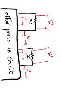
Bellow I have draw a schematic of my circuit. the major of 'other part of circuit' is a rectified transformer.
I want to measure v3 and v6 with an adc, then do some calculation and protection.
v3 is about 30mv to 300mv and v6 is about 150v.
v1 and v2 are 300v max.
v4 is about 4v and v5 about 150v.

so my question is how to do it best,


**broken link removed**

second question is, if i use a differential opamp, how to connect it to adc? I have to use a differential adc?
since I can not connect micro-controller gnd to the any other part of measurement circuit, how is it possible to use a differential adc?


thanks.
 

Hi,

you refer V1, V2, V4, V5 to GND.

Is this always the same GND?
Is this the same as ADC_GND?
***

You say V1 and V2 are 300V max.
What is the min voltage of V1 and V2?

And what waveform is it? (do you expect DC, or AC? What frequency? Is it noisy?

Klaus
 

I think the attachment have problem openning, so I upload it again.


you refer V1, V2, V4, V5 to GND.

Is this always the same GND?
Is this the same as ADC_GND?

no!, Gnd in circuit is the transformer tank, and gnd in adc is output of 7805, which is middle point of a full wave rectifier, although I probably can connect these together but it is preferred not to.

You say V1 and V2 are 300V max.
What is the min voltage of V1 and V2?

about 50 -30v.


And what waveform is it? (do you expect DC, or AC? What frequency? Is it noisy?

1- I can't understand the difference, I though the max voltage is essential.
2- it's a DC waveform(it is output of a filtered rectified ac voltage), a little noisy, and this DC voltage is time varying but about 1v/day!
 

Hi,

about 50 -30v.
This is plenty for a current source solution, like the high side current sense amps work.

I doubt there is a ready to buy current sense amp for that high voltage, but with an opamp and a couple of additional parts you could build your own.

Klaus
 

Status
Not open for further replies.

Part and Inventory Search

Welcome to EDABoard.com

Sponsor

Back
Top