Continue to Site

Welcome to EDAboard.com

Welcome to our site! EDAboard.com is an international Electronics Discussion Forum focused on EDA software, circuits, schematics, books, theory, papers, asic, pld, 8051, DSP, Network, RF, Analog Design, PCB, Service Manuals... and a whole lot more! To participate you need to register. Registration is free. Click here to register now.

Problem with reading ADC with Arduino using AD7401

Status
Not open for further replies.

pero691

Newbie level 4
Joined
Apr 8, 2016
Messages
7
Helped
0
Reputation
0
Reaction score
0
Trophy points
1
Activity points
56
Hi,
Im use arduino mega to read adc 16 bit AD7401 https://www.analog.com/media/en/technical-documentation/data-sheets/AD7401.pdf
I use it for measure voltage drop on shunt resistor for measuring current.
In datasheet -200mV is 12288 and +200mV 53248. So 0V should be 20480 but values i read are strange.
Code:
#include <SPI.h>

byte highByte;
byte lowByte;
unsigned int i_out;


void setup() {

  Serial.begin (115200);                                                                        
  SPI.begin();
  SPI.setClockDivider(4);
  SPI.setBitOrder(MSBFIRST);
  SPI.setDataMode(SPI_MODE0);
}


void loop() {

// read 16bit data ADC
  highByte = SPI.transfer(0x0);
  lowByte = SPI.transfer(0x0);
  i_out = highByte << 8;
  i_out = i_out | lowByte;

  Serial.print("highByte: ");
  Serial.print(highByte);
  Serial.print("   lowByte: ");
  Serial.print(lowByte);
  Serial.print("   i_out: ");
  Serial.println(i_out, DEC);
  delay(250);
}

here is exampe of values i get with 0V on input on adc:

Code:
highByte: 69    lowByte: 229   i_out: 17893
highByte: 140   lowByte: 128   i_out: 35968
highByte: 50    lowByte: 217   i_out: 13017
highByte: 131   lowByte: 0     i_out: 33536
highByte: 44    lowByte: 179   i_out: 11443
highByte: 44    lowByte: 222   i_out: 11486
highByte: 102   lowByte: 183   i_out: 26295
highByte: 140   lowByte: 128   i_out: 35968
highByte: 67    lowByte: 44    i_out: 17196
highByte: 128   lowByte: 131   i_out: 32899
highByte: 50    lowByte: 217   i_out: 13017
highByte: 128   lowByte: 0     i_out: 32768
highByte: 136   lowByte: 8     i_out: 34824
highByte: 128   lowByte: 1     i_out: 32769
highByte: 129   lowByte: 0     i_out: 33024
highByte: 128   lowByte: 130   i_out: 32898
highByte: 38    lowByte: 101   i_out: 9829
highByte: 129   lowByte: 8     i_out: 33032
highByte: 102   lowByte: 67    i_out: 26179
highByte: 44    lowByte: 214   i_out: 11478
highByte: 102   lowByte: 179   i_out: 26291

Thanks.
 

The data as posed at the table above don't give us comprehensible information. To better assess its consistence would be recommended you calculate the real result as being (lowByte+highByte*256) and then plot at a cartesian graph, or at least put at another table, but now ordered ( ascending, descending ).

By the way, according to the datasheet, the AD7401 is not an A/D converter, but a modulator.
 

Hi,

In datasheet -200mV is 12288 and +200mV 53248. So 0V should be 20480 but values i read are strange.
Mid scale = 0V = (12288 + 53248) / 2 = 32768
Not 20480.

Please show us your circuit.

Klaus
 

I changed calculation to i_out = ((lowByte + highByte) * 256);
but now i have values like for max input voltage.
Code:
highByte: 203   lowByte: 44   i_out: 63232
highByte: 178   lowByte: 203   i_out: 32000
highByte: 44   lowByte: 178   i_out: 56832
highByte: 203   lowByte: 44   i_out: 63232
highByte: 178   lowByte: 203   i_out: 32000
highByte: 50   lowByte: 203   i_out: 64768
highByte: 44   lowByte: 178   i_out: 56832
highByte: 203   lowByte: 44   i_out: 63232
highByte: 179   lowByte: 44   i_out: 57088
highByte: 178   lowByte: 203   i_out: 32000
highByte: 44   lowByte: 203   i_out: 63232
highByte: 44   lowByte: 178   i_out: 56832
highByte: 204   lowByte: 178   i_out: 32256
highByte: 203   lowByte: 44   i_out: 63232
highByte: 178   lowByte: 204   i_out: 32256
I will make cartesian graph to see it better.
Sorry for wrong calculation.
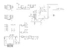
power-board.jpg

Thanks.
 

Maybe I did not explain so clearly.
I meant you should get the values from post #1, and so:

  • Create a new table, the 1st column called e.g Value being the result of (lowByte + highByte* 256)
  • The 2nd column, you keep the values you already took for i_out.
  • Order in Ascendent mode, for instance.
  • Use some online tool to build the graph; I never used them, but you could try for instance this or this.
 
Last edited:

Hi,
I have a graph i hope it is ok. Graph - [iTools.SubhashBose.com].png
 

Hi,

i_out = highByte << 8;
i_out = i_out | lowByte;

Is the same as: i_out = lowByte + highByte × 256

But: ((lowByte + highByte) * 256) is wrong

***
I don't understand your schematic. I find it hard to read.
* R2 is completely useless
* What is the function of R1, R3, R4, R33, R34? It could be compressed to 1 (max 2) resistors
* How do you ensure that IM1 and IM2 is within common mode input voltage range?
* Where does MDAT go to? Where is the SINC IC?

Klaus
 

But: ((lowByte + highByte) * 256) is wrong

You're totally right.
Although I gave the correct formula at post #2, on post #5 it was wrong ( now it is fixed ).

Anyway, at the post #2 it was mentioned that AD7401 isn't exactly an A/D converter, and perhaps will not work as OP expects.
 

Hi Andre,

My post was referenced to post#4. Here is the first occurance of the wrong formula.

Since the IC is a delta sigma modulator it needs a SINC filter to reconstruct the ADC value. I can'find the filter.

Klaus
 

Hi, this schematic is one of boards from servo drive. I want to use this power board but i want to control it with arduino board. MDAT originaly goes to DSP 2407. I dont have this board with me. SINC filter is hw or sw?
 

Hi,

I'm a bit confused..
Without a SINC filter .... where do you have your ADC values (highByte, lowByte) from?

It seems you read the values with SPI, but ther are no SPI lines on your schematic. (MOSI, MISO, SCK, SS)

****
BTW: A SINC filter can be hardware or software.
Did you read the AD7401 datasheet?

Klaus
 

This servo drive i have is not made by me i just want to use it in my project. I use power board for h-bridge and i want to read current also. So im trying to get work this modulator with arduino because its onboard. Do you think its possible to read AD7401 with arduino/mega2560 or its waste of time?

Thanks.
 

Hi,

Do you think its possible to read AD7401 with arduino/mega2560 or its waste of time?

1) you need a hardware connection between AD7401 and arduino. I can't see how you do this.
2) you need code

For sure it is possible. But you don't tell how you want to convert the AD7401 datastream into ADC values.

I told you it can be done with hardware (read datasheet, FPGA) and you could do this with software (you need to read how the reconstrution works).

From datasheet:
To reconstruct the original information, this output needs to be
digitally filtered and decimated. A Sinc3
filter is recommended
because this is one order higher than that of the AD7401 modu-
lator.

And in datasheet there is a chapter "Digital Filter", with the complete information on how to do it.

Klaus
 

My idea of hw connecion is arduino clk -> MCLKIN on AD7401 and MOSI <- MDAT. I know its not made for spi communication but clock frequency for AD7401 is 5-20 MHz and if i will just toggle output pin on arduino instead spi clk frequency would be much lower.
 

Hi,

MCLK needs to be a continous clock, recommended is 16MHz. Usually not gated, no gaps.

MDATA is a serial bitstream coming from the modulator.

Both signals have nothing to do with SPI.
I see no way to connect both devices this with SPI.

Repeatedly: read the datasheet. There is all the information you need to know.

Klaus
 

Ok i see.. I understand it now, my idea was wrong. I will start from beginning. Sorry for misunderstanding im beginner in these things. Thanks again for leading me right way.
 

If you need to read current from a shunt resistor you can use the ADS1115 which is an I2C 16bit converter I use it in some of my projects. There cheap enough from eBay and plenty of samples out there to get you going.
 

Status
Not open for further replies.

Similar threads

Part and Inventory Search

Welcome to EDABoard.com

Sponsor

Back
Top