Continue to Site

Welcome to EDAboard.com

Welcome to our site! EDAboard.com is an international Electronics Discussion Forum focused on EDA software, circuits, schematics, books, theory, papers, asic, pld, 8051, DSP, Network, RF, Analog Design, PCB, Service Manuals... and a whole lot more! To participate you need to register. Registration is free. Click here to register now.

IR2110 circuit for three phase BLDC motor driving

Status
Not open for further replies.

PRABAKARDEVA

Full Member level 2
Joined
Sep 16, 2013
Messages
127
Helped
2
Reputation
4
Reaction score
2
Trophy points
1,298
Location
Chennai
Activity points
2,168
Hi,

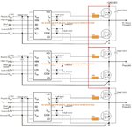
I have designed a circuit for driving the three phase BLDC motor using IR 2110.

I got the Ir2110 circuit form a website which is attached below.

Also I designed the circuit in PCB board.

For checking the PCB board working, interface the normal 12v dc motor with the circuit. ..I don't know that this is the proper way for checking the circuit.

but i couldn't able to drive the motor.

And I generated a PWM pulse from the LPC 1343 microcontroller.
Inputs given to the ic
Vdd-5v/12v
Vcc-Vdd
Vss-Gnd
SD-GND
Hin-PWM
Lin-Gnd
Com-Gnd


But i checked the output voltage in HO which is very low.0.3v something i got.

In LO i got zero volt.

I also checked the Vs pin got 9v.

My question is How much voltage will i get in HO.when i give 3.3v in Hin pin?

What is the use of vs pin and vb pin?

Which is important to drive the mosfet gate and how much voltage should i need?
 

Attachments

  • IMG-20160322-WA0088.jpg
    IMG-20160322-WA0088.jpg
    151.9 KB · Views: 676

Bootsrep capacitors charging only during low side mosfet switching on. So this schematic will never work in static mode. Low side mosfets usually controlled by PWM. And I don't see current sensors anywhere. You planning to use passive mode only? No feedback?
 

Bootsrep capacitors charging only during low side mosfet switching on. So this schematic will never work in static mode. Low side mosfets usually controlled by PWM. And I don't see current sensors anywhere. You planning to use passive mode only? No feedback?


Thanks for the reply..

Can't we control the high side mosfets by PWM?

Yeah..I used this only in passive mode.
 

I explained it pretty clearly. Capacitor between Vb and Vs charging when LO gate is opened. Than it discharges to HI gate.
 

Hi as u advised I have given 50% duty cycle of PWm from the microcontroller to the Lin but i received 2.03v voltage at HO.

I have maintained constant voltage at hin as 3.3v

In Vs Pin also i received 2.03v
In vb pin i received 4.49 v
for vdd i give 5v supply
 

Replace motor with 3 resistive loads, apply >=12V and check again. 5V it not enought.
 

Actually i didn't connect the motor for testing...

When give the pulse on Lin We didn't get the 12v in Hin....

How much voltage will bootstrap capacitor get charged for 1uf capacitor?
 

Inputs given to the ic
Vdd-5v/12v
Vcc-Vdd
Vss-Gnd
SD-GND
Hin-PWM
Lin-Gnd
Com-Gnd
I don't understand what's the actual VDD and VCC voltage.

Required according to datasheet:
VCC 10-15V, usually 12V
VDD depending on logic input level. With 3.3V logic, VDD must be 3.3V too. Usually 5V VDD and 5V logic levels.

HIN and LIN must be driven with complementary PWM signals. Dead time usually required.

As Easyrider83 explained, HO can only work if LIN is periodically activated to recharge the bootstrap capacitor.
 

Thanks for the reply fvm....


Can you please explain How to generate complementary PWM signals and deadtime using lpc 1343?

I haven't done that before...please give me a hint
 

No reason to use PWM for HI side transistors. No reason to use complementary PWM with current schematics. Just 3 PWM channels and 3 GPIO. And timer interrupt to change duty cycle and pin state.
 

No reason to use PWM for HI side transistors. No reason to use complementary PWM with current schematics. Just 3 PWM channels and 3 GPIO. And timer interrupt to change duty cycle and pin state.
I see your point. A BLDC can be driven with only low side PWM and high side switched according to rotor angle, controlled e.g. by hall sensors. Problem is however that the bootstrap circuit can't start from zero speed without an auxiliary charge pump supply.
 

That's true. For this purpose acceleration works in a passive mode according values stored in table. Anyway, this such task like a motor control is advanced and requires powerfull skills.
 

Thns for the reply..fvm

Can you please explain How to generate complementary PWM signals and deadtime using lpc 1343?

I haven't done that before...please give me a hint
 

I think IR2110 has a cousin that is actually meant for driving three phase devices but I cannot recall the number or the source. Of course you will have to still use 6 mosfets but only one driver...
 

then what should i do for generating complementary pwm signals?

As already mentioned above, there is no need to generate complementaru PWM signals. The upper side of the leg can switch at low frequency, and the high side of the leg can switch at low frequency.

Once you are driving a 3-phase BLDC motor, it is assumed you are generating a sinusoidal output.
 

How can i calculate commutation sequence table for bldc motor?
 

Status
Not open for further replies.

Similar threads

Part and Inventory Search

Welcome to EDABoard.com

Sponsor

Back
Top