upervaiz
Junior Member level 2
Hello,
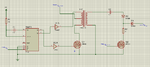
How can i calculate a ferrite core transformer primary number of turns, if i have a variable frequency pulse at the input of the transformer.
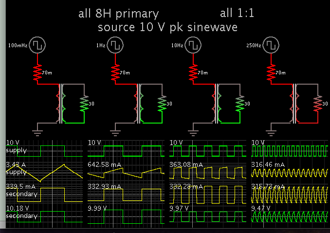
My frequency range is 0.1 HZ to 250 HZ.
How can one design a variable frequency transformer. ??
Your help will be appreciated.
Thank you
How can i calculate a ferrite core transformer primary number of turns, if i have a variable frequency pulse at the input of the transformer.
My frequency range is 0.1 HZ to 250 HZ.
How can one design a variable frequency transformer. ??
Your help will be appreciated.
Thank you
")