Continue to Site

Welcome to EDAboard.com

Welcome to our site! EDAboard.com is an international Electronics Discussion Forum focused on EDA software, circuits, schematics, books, theory, papers, asic, pld, 8051, DSP, Network, RF, Analog Design, PCB, Service Manuals... and a whole lot more! To participate you need to register. Registration is free. Click here to register now.

Sensing Current - Help filtering

Status
Not open for further replies.

unavezmasysale

Member level 2
Joined
Mar 24, 2014
Messages
49
Helped
1
Reputation
2
Reaction score
1
Trophy points
8
Activity points
353
Dear,

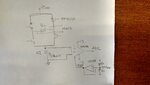
I am sensing current over a shunt resistor, to achieve this I sense the voltage over the 1ohm shunt resistor.

As you can see in this image:

Shunt_Voltage.jpg

This is the voltage at the ADC input. Before the ADC the shunt resistor signal is connected to a AO INA118.
As simple as this, the voltage is connected to the INA118, and the INA118 is connected to the ADC (DSP MC56F8006 NXP - ex Freescale).
I need to know what do you recommend to improve the signal.

Best regards,

Carlos.
 
Last edited by a moderator:

https://www.ti.com/lit/ds/symlink/ina118.pdf

what is the time base on your scope shot?

Where is this resistor, is it somewhere in a switching power supply?

Was the scope shot done with a neatly terminated bit of x1 coax, or with a scope probe with its gnd lead dangling all over the place.?

What is the pcb layout like….are all the signal traces routed in diff pair style?..low as possible loop area?

Have you got an RC filter across the sense resistor?

If you remove the probe from the resistor, do you still see all that noise? (with the scope lead in roughly the same physical place)
 

Hi,

Please post schematic, pcb layout and all related informations.

Switching frequency, ADC sampling frequency..what do you want to calculate with the ADC values? Rms, peak, average....
How often do you need a calculation result?

Klaus
 

https://www.ti.com/lit/ds/symlink/ina118.pdf

what is the time base on your scope shot?

20mS

Where is this resistor, is it somewhere in a switching power supply?

After a H Bridge.
SCH_Shunt.jpg

Was the scope shot done with a neatly terminated bit of x1 coax, or with a scope probe with its gnd lead dangling all over the place.?

...with a scope probe with its gnd lead connected to GND.


What is the pcb layout like….are all the signal traces routed in diff pair style?..low as possible loop area?

As I had to change the first circuit of sensing current, the connection between shunt resistor and INA118 is through a twisted pair and not in the same board.

Have you got an RC filter across the sense resistor?
No.

If you remove the probe from the resistor, do you still see all that noise? (with the scope lead in roughly the same physical place)

I do not understand this.


This is the testing circuit:
Circuito.jpg

Circuito_Label.jpg

- - - Updated - - -

Klauss,

20Hz.
Conversion time 23uS.
I need Vrms over the shunt resistor to know the current. After I could know this value I check the voltage over a resistor that is in the center of the HBridge, so I can calculate in a indirect way the the value of this resistor.
The final application is geological survey.

Thanks,
 

Attachments

  • SCH_Shunt.jpg
    SCH_Shunt.jpg
    3 MB · Views: 54
  • Circuito.jpg
    Circuito.jpg
    3.4 MB · Views: 65

OK THANKS, BUT I CANT SEE TWISTED PAIR, ALL I SEE IS A LOT OF LONE WIRES, (sorry about capitals)..each wire should be taken with its "return", so as to reduce loop areas...but if you are switching at that slow rate, then cant you just shove an RC filter at the input to the INA then its job done ?.....i mean, you could buffer it, then rc filter it, if you wanted, then just wait for the reading to settle out from the filter time constant and take the reading with adc when its settled out.really the adc and the ina and the shunt resistor shoudl best be close on the board, or at least the ina and the adc be close.
can you just clip the gnd clip to the probe tip and see if all the noise is still there?..if it is, then its obviously just background noise in the scope lead, and not necesarily in your cct..
 
Treez,

can you just clip the gnd clip to the probe tip and see if all the noise is still there?..if it is, then its obviously just background noise in the scope lead, and not necesarily in your cct..

I am not sure about this test. Do you want that I sense but without the GND pin of oscilloscope connected?
 

Hi,

Only 20Hz, sure?

23us means 43.5kHz?
So you have about 2150 samples per full wave.
That's a lot.

Place the ina close zo the adc.
Find a good gnd connection and connect RC low pass filters to each ina input. Fc about 100Hz.
This should filter away the high frequency parts.
There will be noise remaining...
If you have a fixed relationship between sample_frequency to output_frequency (2150?) Then you should average exactely that count of squared samples for the rms calculation.
I don't think that the error caused by the remaining noise will cause more than some %. (With the given waveform).

What precision do you need?

Klaus
 
KlausST,
Yes, the signal frequency is 20Hz (the signal of the first post).

I´m working with Processor Experts, it let configure the conversion time (I set it to 23uS) and number of conversions (I set it to 20). So the result of the ADC is an average between 23uS x 20 samples. What frequency do you recommend to set for my frequency?

For the RC filter, what kind of capacitor do you recommend? Ceramic could be useful if the precision is not a must?

Thanks.
 

Hi,

Capacitor. Yes, i tend to ceramics. X7R, (don't use Z5U). Film are even better.
I'd go for a 1k resistor (or even lower) , then a 1.5uF capacitor.


Why only 20 samples? I'd say the more the better.

Klaus
 

Treez,


I am not sure about this test. Do you want that I sense but without the GND pin of oscilloscope connected?

Treez,

I think that I understood what you were asking me. I have connected the GND clip to the probe to see the noise in the oscilloscope and I have realized that the oscilloscope noise is 10mVpp.

See the attached picture:
IMG_20160326_134019427.jpg
 

is that with the scope lead situated in roughly the same physical place that it was in when it was probing the circuit?
 

is that with the scope lead situated in roughly the same physical place that it was in when it was probing the circuit?

No. So now I think that I did not understand you.

You suggest that I must put the lead in the same place when I sense the current (first image of this thread). So I do not understand where I must connect the GND clip. Sorry.
 

This test is just trying to find out how much of the noise you got in your first scope shot is simply just noise induced into the scope lead by the ambient noise in the vicinity of where the scope lead is situatied.

If you have a noisy smps, start it up, and put it next to the scope lead, and you will see the induced noise into the scope lead.

When you look for noise induced in the scope lead, as discussed, the position of the scope lead in relation to noise sources makes a difference, also, the gnd clip needs to be clipped to the probe tip, or else you will pick up a lot more noise than you would have gotten with your scope probe in circuit and connected across the 1 ohm resistor.

In fact , if you just look at the scope signal with the gnd clip and probe tip totally unconnected, you will notice that it picks up the 50Hz sine wave of the mains electricity fields that is around you.

Treez,

Now it was very clear.

This image is the noise sensed by the lead in the nearest ambient of the shunt resistor. The GND clip was not connected:
IMG_20160326_151444156.jpg

The noise does not seem to be a problem I think and the 50Hz signal is very noticeable. The oscilloscope scale for the voltage is 20mV.
 

ok, and now the next thing is to scope the resistor with a probe lead which doesnt have a dangley ground lead which picks up noise.......but you will not be able to buy this, you must select some coaxial cable, cut a 1 metre length or so, and modify it so that you can solder the outer sheath and the inner wire to across the resistor , for the most noise free scoping of the voltage......it is x1 so put scope on x1
Any contract electronics manufacturer will be able to make this for you and they probably have stocks of coax so you dont have to buy the whole reel when you only want about
a metre...get one with the right characteristic impedance for your scope..probably 50 ohms.

But then again, once you have heavily filtered it (and layed the pcb well) you may trust that it is a noise free signal anyway, and just ignore the noise you see on the scope.
 

Status
Not open for further replies.

Similar threads

Part and Inventory Search

Welcome to EDABoard.com

Sponsor

Back
Top