Continue to Site

Welcome to EDAboard.com

Welcome to our site! EDAboard.com is an international Electronics Discussion Forum focused on EDA software, circuits, schematics, books, theory, papers, asic, pld, 8051, DSP, Network, RF, Analog Design, PCB, Service Manuals... and a whole lot more! To participate you need to register. Registration is free. Click here to register now.

[SOLVED] Why is an input bias current of an opamp constant?

Status
Not open for further replies.

CHL

Member level 3
Joined
Jan 20, 2015
Messages
60
Helped
2
Reputation
4
Reaction score
2
Trophy points
8
Activity points
550
Hello

When we consider an input bias current of an opamp, it is constant.

For example, if there is a simple inverting amplifier without an input signal, the output voltage will be the input bias current x the feedback resistor, and the output voltage only depends on the feedback resistor.

Why is the input bias current constant?

Why isn't it affected by the resistor or input impedance?

For JFET input opamps, the reverse biased pn junctions of the input FET provide almost constant currents.

However, I don't understand BJT and MOS based opamps.
 

The input current of an opamp that has bipolar transistors on its inputs is very low. They are made so that the input bias current does not change with voltage or temperature changes.
An opamp with Jfet or Mosfet inputs has NO bias current, instead it is extremely low leakage current.

The output voltage of an opamp IS NOT the bias current x the feedback resistor, instead the output voltage is the input voltage x the gain set by negative feedback. The input bias current is so low that it barely affects the output voltage.
 

Hi,

The input stage of an opamp consists of two input transistors.
Both emitters are connected to a common current source.

In a normal opamp situation (non saturated input stage) the constant current is about divided into two equal emitter currents.
This emitter current is divided by the transistor dc current gain --> giving the base current.

Klaus
 
  • Like
Reactions: CHL

    CHL

    Points: 2
    Helpful Answer Positive Rating
The input current of an opamp that has bipolar transistors on its inputs is very low. They are made so that the input bias current does not change with voltage or temperature changes.
An opamp with Jfet or Mosfet inputs has NO bias current, instead it is extremely low leakage current.

The output voltage of an opamp IS NOT the bias current x the feedback resistor, instead the output voltage is the input voltage x the gain set by negative feedback. The input bias current is so low that it barely affects the output voltage.

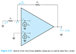
Yeah you are right if there is an input signal. However, as I said, the output voltage is the input bias current x the feedback resistor when there isn't the input signal. (Please see Sedra Smith book)

Also, MOS input opamps have input bias currents. The example is below.

http://cds.linear.com/docs/en/datasheet/626810f.pdf

I think the currents are leakage currents, but the term is 'bias' currents.
 

Hi,

However, as I said, the output voltage is the input bias current x the feedback resistor when there isn't the input signal.
I´m no friend of this definition.
1) what does "no input signal" mean?
* Open = disconnected, then the only resistor is the feedback_resistor. But then it is no "inverting amplifier" circuit.
* GND = 0V, then the formula is not true

2) The formula is not exact in either way. It should at least be: V_Out = V_input_offset + I_Bias x feedback_resistor. (With the non_inverting input to GND.)
... it depends on offset_voltage, bias_current, feedback resistor .. wich one causes the most output_voltage

... i´m not sure if this discussion and especially this formula helps you to understand OPAMPs. Bias_current is just a detail, and in many circuits one can ignore it.
I recommend to focus on the basic function of an (ideal) OPAMP first, then if you undersatd it completely go to the details of a (non ideal) OPAMP.

Klaus
 

Hi,


I´m no friend of this definition.
1) what does "no input signal" mean?
* Open = disconnected, then the only resistor is the feedback_resistor. But then it is no "inverting amplifier" circuit.
* GND = 0V, then the formula is not true

2) The formula is not exact in either way. It should at least be: V_Out = V_input_offset + I_Bias x feedback_resistor. (With the non_inverting input to GND.)
... it depends on offset_voltage, bias_current, feedback resistor .. wich one causes the most output_voltage

... i´m not sure if this discussion and especially this formula helps you to understand OPAMPs. Bias_current is just a detail, and in many circuits one can ignore it.
I recommend to focus on the basic function of an (ideal) OPAMP first, then if you undersatd it completely go to the details of a (non ideal) OPAMP.

Klaus

ib.png

This image is from the Sedra Smith book
 

Hi,

Yes, I see... without taking offset voltage into account it is true for open input as well as for grounded input.

What can we learn from that?

Klaus
 

The opamp you posted the datasheet for has an input leakage current (they call it a bias current because in the olden days.....) of 31 femto-amps and a 20k feedback resistor. Then the output voltage caused by the leakage current is 31 femto x 20k= 0.000000000062V which is so close to nothing that everybody calls it ZERO.
A bias current is either positive or negative depending on whether the input transistors are NPN or PNP. A tiny little leakage current could be positive OR negative.

That's true because the datasheet is for the Ultra-Low Bias Current FET Input Op Amp.

My question is why the leakage current is independent (or constant) as shown in the textbook.
 

Bias current for the forward biased base-emitter of an older normal opamp remains constant if it is designed to be constant (an LM324 example). But leakage current in input Jfets or Mosfets increases with increased voltage and with increased temperature.
 
  • Like
Reactions: CHL

    CHL

    Points: 2
    Helpful Answer Positive Rating
In contrast to legacy LM324 or LM741, many modern OPs with bipolar input stages provide input current compensation. Their input current is the remaining compensation error, not the input transistor base current. It's much smaller than a typical bipolar transistor base current but more affected by temperature and voltage variation and without a specified polarity. Input current compensation can be already found with pretty old OP07.

Referring to the present discussion, it appears more like a leakage than a defined bias current.

I suggest to review actual OP datasheet instead of talking up an antagonism of leakage and bias.
 
  • Like
Reactions: CHL

    CHL

    Points: 2
    Helpful Answer Positive Rating
Status
Not open for further replies.

Part and Inventory Search

Welcome to EDABoard.com

Sponsor

Back
Top