Continue to Site

Welcome to EDAboard.com

Welcome to our site! EDAboard.com is an international Electronics Discussion Forum focused on EDA software, circuits, schematics, books, theory, papers, asic, pld, 8051, DSP, Network, RF, Analog Design, PCB, Service Manuals... and a whole lot more! To participate you need to register. Registration is free. Click here to register now.

[moved] MC34063 Boost Configuration Voltage Drop Under Load

Status
Not open for further replies.

sonar_abhi

Member level 1
Joined
Mar 15, 2016
Messages
36
Helped
2
Reputation
4
Reaction score
2
Trophy points
8
Activity points
380
Hello Guys,

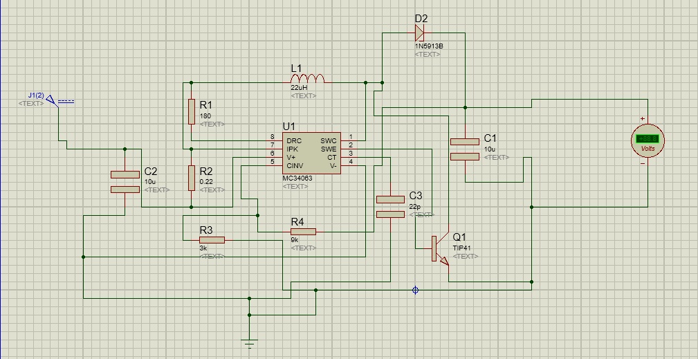
I am facing a problem working with MC34063 under standard Boost configuration. Vin is 3.2V and Vout is 5V. Iout is 375mA.
When checked on a DMM, the Vout is 5V but if even a small load is applied, say a microcontroller, the voltage drops to 1.5V.
The component values are as follows:
Rsc: 0.22 ohms
R: 180 ohms
Cin: 10uF
Cout: 10uF
L: 22uH
R3:R4 (for 5V): 3.3K and 10Kohms
Diode: 1N5817
Can anybody please help?

Abhishek
 

Hi,

We need YOUR schematic and YOUR pcb layout to verify the circuit.
And we need the types/ordering codes of the used parts. Especially all Cs and Ls.

For example: a 10uF standard mains frequency electrolytic capacitor may not work while a 10uF X7R may work.

Klaus


This is the schematic. I have made the circuit as per the standard boost configuratuon diagram.

The Ct is 22pF. Component Values are as per the online calculator situated at www.nomad.ee/micros/mc34063
And I have also calculated the values as per the application note.
 

I think you need to see note 6 of page 3 of the datasheet, I do not think you are getting enough transistor drive current to drive your internal bjts properly.
The 180 ohm doesn't let enough current through with your 3.3v input

- - - Updated - - -

Also, what value capacitor are you using to set the switching frequency? This is needed as your L value means very little without the fsw value

- - - Updated - - -

I make it that you need to replace your 180 ohm resistor with a 6 ohm , 1 watt resistor, and this is for a 50khz op frequency with a 22uh inductor.

Your peak fet current is 2.3A, and your BJT drive current needs to be at least 1/10th of this.

The alternative is to use the darlington configuration...however, that has a higher VCE of the BJT....however, I think because your current is so high (relativey speaking), you will have to go to the darlington configuration, ie connect pin 1 and 8 together, and avoid the 180 ohm resistor

- - - Updated - - -

Actually I think you need the figure 9 setup as your peak current is so high.......your vin is 3.2v, but after subtracting the 0,7v of the vce(on) you are down to 2.5V effectively.

- - - Updated - - -

If you don't like the external transistor then try one of the micrel monolithic boost chips instead.

The MC34063 looks like a great chip at first site, but then you look deeper and see the high drive current, the high Vce(on) in darlington config, the 7mA that goes into the internal 100 ohm resistor, the 2us delay in switch_off that occurs if you use the non darlington configuration.................the limitation in switching frequency that arises due to the 2us delay....................then you realise that the mc34063 is only for very low power situations where you want a dip package.
 
Last edited by a moderator:

Don't know how you calculated it, but CT of 22 pF is beyond a reasonable range. The device can't switch that fast and will convert most of the input power into switching losses, leaving about no available output current.

I don't believe that MC34063 is well suited for about 2W output with 3.3V input.
 

right ive just seen your second post sonar_abhi...I see you are using the external transistor.


mc34063 datasheet
https://www.sparkfun.com/datasheets/IC/MC34063A.pdf

- - - Updated - - -

tip41 datasheet
https://www.fairchildsemi.com/datasheets/TI/TIP41C.pdf

the vce(on) of tip41 is 1.5v and the vbe(on) is 2v, this is not a good candidate for your low vin application, do you really want to persevere with mc330463?....or use micrel?

- - - Updated - - -

I also notice you missed the vbe resistor on the external bjt

- - - Updated - - -

if you want to try and get something out of your circuit then

Use a 0.1 ohm sense resistor (rated to 1w)
Change to a 47uh, 2.7a (min) inductor.
Change to 30khz switching frequency.

And recalculate your drive resistor.

....uuuuuhh...just realised that the sense resistor drops another 0.3v, ..so that's more of your precious vin gone....means more peak current still. (thought it best to give these sentiments as it shows you the considerations here with mc34063)
 

Hello Guys,

I made several changes in the circuit and tested in for the following changes:
1] Inductor: 22uH/2A
Shorted the pins 1 and 8 (to use it in a darlington configuration)
Timing capacitor: 390pF
Output capacitor: 100uF/16V
Removed the external transistor and checked it with transistor also

2] Inductor: 42uF/2A
Shorted the pins 1 and 8 (to use it in a darlington configuration)
Timing capacitor: 470pF
Output capacitor: 1uF/16V
Removed the external transistor and checked it with transistor also

Still the same problem persists. The output voltage at no load is 5V proper but under load, it drops to 3.2V.

The reason I persisted with MC34063 was its low cost (it costs Rs. 10/piece in India compared to Rs. 60/ piece for Micrel MIC2288) and that there are people who have posted that they have used the MC34063 chip with the same Vin and Vout at 300/350mA. But I guess for me, there is no other option than to use the Micrel chip.

Thank you all for your help.
 

there are people who have posted that they have used the MC34063 chip with the same Vin and Vout at 300/350mA.
Which Iin and Iout? I believe MC34063 can be used for 3.3 to 5V boost, but efficiency will be low. Input current for Iout of 350 mA hardly below 0.7 to 0.8 A.-
 

what is the esr of the inductors?....that will drop more voltage.....wth mc34063 you are loosing over half your vin with all the voltage drops...the darlington Vce is 1.5V...so there's half your vin gone just from that alone.
How have you sized your sense resistor?
1uf sounds too small for output cap. Stick with the 100uf.
You could play around with it and see what is the maximum load that you can supply at 5v before it drops out.
Set your sense resistor to the minimum it can be (0.3v/1.5a = 200 milliohms), then put the 47uh, 2a inductor back on, and see what it gives you before dropping out.
Check the output divider is correct, on no load it can be wrong and still give 5v at first due to the input surge.
 
Last edited by a moderator:

Hi,

I still think it may be a PCB layout problem.
Just by viewing at the chaotic schematic of post#3.

There may be a reason why he doesn´t show...

Klaus
 

@treez, I dont have anything to measure the ESR of the inductor.

Right now I am testing with a 350mA LED at the output, and the voltage is dropping to 3V. But even if I drive a microcontroller, the voltage drops out. As soon as I disconnect the load, voltage climbs back to 5.2 V.

@KlausST, I am testing the circuit on a breadboard and although I dont know much, I doubt whether the placement of components would be that critical for a legacy chip like MC34063. Apologies if I am wrong.

@FVM, I understand that the efficiency would be very low but again it is more about getting the output at 5V/350mA for a very short period hence I can live with low efficiency for a short period.
 

Hi,

Right now I am testing with a 350mA LED at the output, and the voltage is dropping to 3V.
3V forward current is not unusual for a 350mA LED. Are you sure it is specified to be 5V@350mA.
LEDs usually are current dirven, not voltage driven. Check o this.

I am testing the circuit on a breadboard
I don´t think a breadboard is suitable for power switching applications. Special care needs to be taken with GND connections.

Klaus
 

No, LEDs are not the end application. I am using them to test the voltage stability at 350mA load.
 

i am not sure how you are using the led AS A load, beware, cuzz a single led will Just clamp the vout to its vf, . anyway, you say have problems when load is just a micro, so it cant be that problem.
OK, so it is on breadboard.....that is problem, because the current sense resistor inputs are senstive comparator inputs and there could well be problem there with noise into them. Also, the feedback voltage input may need a 100pf cap, also very close.
You may well have to put 100pf cap as near as possible to current sense pins, but even then, it will be difficult.
 

Ok. So I will get a PCB designed. Any special care that I must take as to the placement of the components and the traces width?
 

Hi,

The output voltage at no load is 5V proper but under load, it drops to 3.2V.
There must be soemthing wrong in your circuit.
With a 5V input voltage i never expect less than 4.4V at the output. Even when the MC is not working.

Then I reviewed your schematic.
--> You used a 1N5913 diode, wich is a 3.3V zener. But datasheet says to use a 1N5819 diode, wich is a schottky.
--> You urgently need to use a schottky diode!

Klaus
 

Well spotted Klaus.
Anyway, just in case the OP needs it, here is SMPS PCB Layout guide.
 

Attachments

  • Basics of SMPS Layout _4.doc
    645.5 KB · Views: 87

Sorry Klaus, forgot to mention that. I have used a 1N5819 in my actual circuit. Couldnt get a simulator model for 5817/19 in Proteus hence substituted what was available for the schematic purpose.
 

to be honest, you could, if you were careful, do a stripboard version of the circuit, but you would have to be careful and use small smd caps and resistors where necesary....and probably need 100pf o6o3's to the sense inputs., -very close to the chip.
Make all current loops very narrow, preferably twisting wires where necesary.
 

Hi,

With a 5V input voltage i never expect less than 4.4V at the output. Even when the MC is not working.
I just recognized it´s 5V output, not input.

Check this:
* connect 3.3 V at the input.
* Connect about 15 Ohms load to the output (making about 0.35A at 5V)

Check voltages step by step:
* Voltage at C2: no voltage drop. it should be near 3.3V
* Voltage at input of R2. No voltage drop. Should be near 3.3V
* Voltage at output of R2: max. 0.05V drop: Should be near 3.25V
* Voltage at input of L1. no additional voltage drop. Should be near 3.25V
* Voltage at the output of L1: max 0.1V additional voltage drop. should be at least 3.15V (I expect about 2.1V average with a non_darlington and 5V output. 68% x 0.5V, 32% x 5.5V)
* Voltage at anode of D2. No additional drop. same as output of L1
* Voltage at C1. 0.1V drop in L1 + 0.4V drop in D2. should be more than 2.75V even when MC is not switching. And about 5V when MC is switching properly.

Klaus
 

Status
Not open for further replies.

Part and Inventory Search

Welcome to EDABoard.com

Sponsor

Back
Top