Continue to Site

Welcome to EDAboard.com

Welcome to our site! EDAboard.com is an international Electronics Discussion Forum focused on EDA software, circuits, schematics, books, theory, papers, asic, pld, 8051, DSP, Network, RF, Analog Design, PCB, Service Manuals... and a whole lot more! To participate you need to register. Registration is free. Click here to register now.

SPI FLASH - MCU layout design

Status
Not open for further replies.

giorgos3924

Junior Member level 2
Joined
Jan 27, 2010
Messages
21
Helped
0
Reputation
0
Reaction score
0
Trophy points
1,281
Activity points
1,463
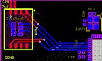
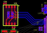
How is my layout of SPI Flash memory?
I am begginer in pcb designing. And i have to route a SPI Flash memory with a wireless mcu chip.

The memory is: S25FL128SAGNFI001
and chip is: TI's CC3200
The blue chip below the flash is resistor pack (pull-ups, 100k).
 

Attachments

  • spiflash.JPG
    spiflash.JPG
    304.9 KB · Views: 286

Not sure why you want pull-ups at all. According to the data sheet, lines such as the RESET# and WP# have internal pull-ups so they can be left unconnected if that is appropriate. The other SPI lines typically are driven (or tri-stated in the case of the MISO line of a deselected chip) and don't need pull-ups.
The only issue you may have is if you are using very high clock frequencies where you may want to use a ground plane and isolate the tracks a little bit - but that means you want to be using the clock speeds around the 133MHz maximum for that chip.
Susan
 

RESET and WP pins are tied to the supply (3.3V). I made the schematic according to the TI's datasheet CC3200 which it use that pullups. Regarding to the layout I assume that there's no need of length matching consideration of that frequency. Please let me know if my intuition is correct. Although I will try to catch the higher speed as possible
 

I assume you mean the data sheet at https://www.ti.com/lit/ds/symlink/cc3200.pdf and the diagrams on pages 58 and 60.
For a start the resistors on the MOSI and CLK lines are pull-down; only the \CS\ line has a pull up.
I can only guess that the pull-downs are there to stop transients occurring during power up and when configuring the SPI interface. The only pull-up that is really needed is on the \CS\ line which will make sure that the memory is deselected until it is REALLY needed.
As for the track length, the difference in length will have no practical effect. At 133MHz, a wavelength is about 2m long! Having said that, unless you have a practical reason to access the memory at that speed, I would suggest you use a clock speed as slow as you can (driven by the required transfer rate) as every trace will radiate and the problem is worse with higher frequencies. This is a reason why ground planes and including inter-track grounds can be useful. From what you have said - I would not get too wound up over this.
Susan
 

The purpose of the p/u and p/d resistors is explained in the datasheet. Because the controller is tri-stating the SPI lines, floating signal could generate considerable additional current consumption of the SPI flash, very bad for a battery operated low power design.
 

Yes, sorry, they are indeed pull-downs.
However, i consulted the Ti's datasheet for that treatment, and i strive to keep my deliberations just in pcb improvements.
 

The purpose of the p/u and p/d resistors is explained in the datasheet. Because the controller is tri-stating the SPI lines, floating signal could generate considerable additional current consumption of the SPI flash, very bad for a battery operated low power design.
I stand corrected. In my defense I had only quickly scanned the data sheets.
Also I have seen the MISO line tri-stated (many times - it is the common way to get multiple SPI devices on the "bus") but the 'chip select, SCK and MISO are normally continuously driven by the master and so the situation would not therefore occur on those lines.
Susan
 

I tried a little bit different layout. I kept distance between traces for ground plane.
 

Attachments

  • spiflash2.JPG
    spiflash2.JPG
    91.5 KB · Views: 130
Last edited:

Status
Not open for further replies.

Part and Inventory Search

Welcome to EDABoard.com

Sponsor

Back
Top