jeff0283
Junior Member level 2
Hi ,
I have designed the output matching with CPWG(cpw with ground) line and L,C component.

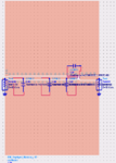

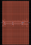
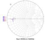
But the result of EM-cosimulation looks strange and different from the result of schematic.
(S(37,37) is for schematic, S(39,39) is for EM cosimulation)
I found the problem.
When I took away the pins on the ground of the CPWG line on my layout, and let the capacitor connected to the ideal ground, the result seems less strange, but is different from the original result.

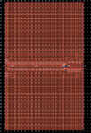
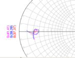
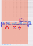
(S(37,37) is for schematic,S(39,39) is for EM-cosim with ground pin on layout,S(41,41) is for EM-cosim without ground pin on layout.)
Does someone know if I should add the ground pin on the layout?
I have designed the output matching with CPWG(cpw with ground) line and L,C component.


But the result of EM-cosimulation looks strange and different from the result of schematic.
(S(37,37) is for schematic, S(39,39) is for EM cosimulation)

I found the problem.
When I took away the pins on the ground of the CPWG line on my layout, and let the capacitor connected to the ideal ground, the result seems less strange, but is different from the original result.


(S(37,37) is for schematic,S(39,39) is for EM-cosim with ground pin on layout,S(41,41) is for EM-cosim without ground pin on layout.)
Does someone know if I should add the ground pin on the layout?