Continue to Site

Welcome to EDAboard.com

Welcome to our site! EDAboard.com is an international Electronics Discussion Forum focused on EDA software, circuits, schematics, books, theory, papers, asic, pld, 8051, DSP, Network, RF, Analog Design, PCB, Service Manuals... and a whole lot more! To participate you need to register. Registration is free. Click here to register now.

20-70V input to 13.8V output, switching step down..?

Status
Not open for further replies.

mr_W

Junior Member level 2
Joined
Dec 15, 2006
Messages
23
Helped
1
Reputation
2
Reaction score
1
Trophy points
1,283
Activity points
1,525
Hi all,
I am working on improving electric installation on older type KTM motorbike, and there is this nasty permanent magnet alternator giving out AC ranging from 20V up to 70V depending on RPM. The idea is to make switching step down regulator that takes this type of input and give out 13.8V for charging just regular Pb accu and running other accessories.

However, given my zero level experience with smps other than using ready-made modules I am clueless on how to proceed with this. In particular, the high end input voltage is giving me trouble, as all of the ready available ICs that would make this easy accept up to 40V give or take some.

What I figured out is that I need simple enough circuit, yet driving external FET able to work with high voltage. Did some research and turned out mc34063 is *not* a good choice, maybe UC3842A?

Vcc for the IC could be taken from battery, actually, is that good direction?

I'd need some pointers, ideas, maybe schematics.. Just something to lighten my way :) Thanks.
 

Hi,

What output current @ 13.8V do you expect?

***
Many manufacturers of step down ICs have interactive selection guides on their internet sites.

Klaus
 

@KlausST

As this is to recharge very small battery and to run lights and signalling, with no more than 100W of power altogether, I guess 10A should be fine. I suppose that is doable as far as mosfet selection goes, but I am of course unsure about other components.

Many of those manufacturers indeed have those selection guides, but integrated stuff is rarely ever rated for more than 40V. And even if there is such IC, it is probably not so commonly available. From what I understand, the most problematic part with all-integrated solution is that Vcc for the IC itself cannot be that high, but with external mostfet I could supply lower Vcc - at first with resistor divider and/or zener diode, just for bootstraping and then from its own output. Also, in my case I could supply the suitable Vcc directly from the battery.
 

It is possible to reduce all voltages which are applied to your control IC. It can be done with zener diode regulation, resistor dividers, etc.

You can drive a switching transistor/mosfet with a low voltage, by making it an N-device placed near 0V ground.
 

@BradtheRad

Yes, all voltages except the main supply that goes to switching element - power mosfet. My goal is to avoid converting excess voltage at high currents ( 10A) to heat, as this would happen with resistors, zeners, etc.

I am fine with small zener and resistor just for bootstrapping the process, providing initial supply, but not for the switching mosfet.

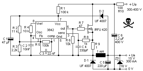
Here is one interesting schematics that I just found, it is almost what I need, but I don't quite understand what is happening here and what is the purpose of output zener. yet alone how voltage is regulated to exactly 15V.

5408392400_1456266175.gif

( original source https://www.joretronik.de/Web_NT_Buch/Kap6/Kapitel6.html )

Also, where the 300mA limit comes from? IRFU420 is rated at least 1.5A continuous. Would larger size mosfet would be able to handle more current?
 

giving out AC ranging from 20V up to 70V depending on RPM. The idea is to make switching step down regulator

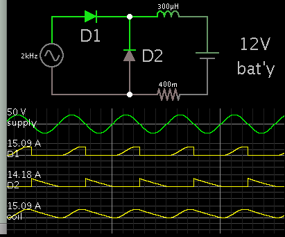
AC can drive a buck converter directly. No need for a switching device. It might be possible to adapt this concept. By putting a battery as the load, you charge it while it automatically creates a volt range of 12-14V.

3420110400_1456270832.png


As rpm goes up, voltage goes up. However that does not mean this converter draws more current. A faster switching speed causes an inductor to draw less current. So you may find that it does not overload at higher engine speeds.

The above schematic draws current for only one-half of the cycle. To use the other half of the cycle, you'll need to add a load. Perhaps another buck converter, made for negative polarity?
 
Now this is quite interesting.

How do I calculate the correct inductor value? I suppose I'd need to know the switching frequency at least, right?

And this resistor at the bottom, is this internal battery resistance, or something else that I'd need to account for?

Thanks!
 

Now this is quite interesting.

How do I calculate the correct inductor value? I suppose I'd need to know the switching frequency at least, right?

And this resistor at the bottom, is this internal battery resistance, or something else that I'd need to account for?

Thanks!

The inductor and battery have some amount of resistance. The low-ohm resistor is just a rough guess. The total for the entire current loop is probably a greater ohm value.

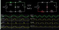
Two simulations at a slow and fast frequency. (I seem to have been wrong about the current level not changing much.)


Ideally you'd experiment with various inductors, to see how what amount of Amperes goes through the system at different speeds. It all depends on how much power is produced by your AC generator.
 

Are your voltage measurements without any load?

Many years ago (over 35) when I was young and restless, :grin: I also had Penton/KTM motorcross bike, powered by a Sachs engine.

My measurements at the time indicated that without a load, the magneto output consisted of higher voltage spikes of very narrow duration, and thus the average voltage was much lower.

Therefore by applying a diode, a cap and a small light bulb, the voltage would drop and its range narrower. Beetween 6 and 14 volts, depending on RPM, if my memory serves me well.

I don't know if this would still apply to your bike.
 

I have built capacitive discharge ignition for this bike, with boost converter to 300V, perfect timing control with MCU, but have learned hard way (busted regulators) that supply voltage will not come down on its own, even with some load. It is simply too high, because of very crude alternator design.

OEM voltage regulators consisted of zener diode and transistor. This device was similar in appearance to high amperage rectifier block, but had two terminals only and was connected in parallel with alternator and load. It seems that its sole purpose was to bring down excess voltage by converting into heat. Now when this fails, it also takes down all the lightning with it. (Now when I think, there is something odd with this setup, but it could be I have forgot something - there should be rectifier also)

Anyway, converting to heat is something that I will simply not accept as 21st century solution ;-)

I did however stumble upon very simple, hopefully effective enough solution. This guy had similar problem and solved it..

https://blogs.itb.ac.id/rollingdice/2013/04/05/avr-tiny-buck-converter/

It is in fact same way I generate high voltage already. So I'll give it a try today.
 

Anyway, converting to heat is something that I will simply not accept as 21st century solution ;-)

.

Fully agree with you on this one.

On your original circuit that you had posted (in German), it is an extremely clever solution to provide tha auxillary voltage (around 12v) that the controller IC requires.
The way L1 is connected, both provides the main output voltage via the D1 loop, and the auxillary voltage via the D2 loop.
Also very clever, the voltage feedback is taken from the secondary loop, although the forward Vd mismatches between the two diodes, will create a small discrepancy.

However if the output becomes unloaded, the feedback has no way to compensate for this problem, as D1 will no longer conduct current. Therefore the output zener creates some a load once the voltage reaches a certain level, to ensure D1 conducts and both the main and auxillary voltages still track together.

The current limit is related in large part to the inductor being used. You don't want it to saturate.
Other components: the diode, capacitors, Mosfet, current sense resistor; would also have to change
 

I would have thought you need to rectify the alternator output, to give DC, then just convert that to 13.8V..with some overcurrent limiting.
What frequency is the alternator output.?
 

mr_W, shouldn't you be looking at this as a battery charger? You want the alternator to charge the battery.

This should be how your system works now. Why are you trying to bypass this mode of operation?

There are lots of ap notes on battery chargers.
 

I was thinking of making it a 13.8V output smps with say a 7 amp current limit, so that it just maxes out at 7 amps when not fully charged. Lead acids are string and can handle that. Most alternators don't bother to have a charger after them, they just dump the current into the lead acid battery.
 

Really you need a 400V 10A or bigger bridge rectifier (assuming just 2 wires out of your alternator, if 3 wires it may well be 3 phase) a cap to smooth it out a bit, then a dedicated buck converter to provide the 13.8 volt to the battery lights etc, this is not a trivial design for 70V max in, and would be a minor challenge for a power electronics engineer of only a few years experience.
 

Status
Not open for further replies.

Part and Inventory Search

Welcome to EDABoard.com

Sponsor

Back
Top