Continue to Site

Welcome to EDAboard.com

Welcome to our site! EDAboard.com is an international Electronics Discussion Forum focused on EDA software, circuits, schematics, books, theory, papers, asic, pld, 8051, DSP, Network, RF, Analog Design, PCB, Service Manuals... and a whole lot more! To participate you need to register. Registration is free. Click here to register now.

Isolation between LC-VCO and loop filter

Status
Not open for further replies.

Debdut

Full Member level 3
Joined
Oct 29, 2013
Messages
174
Helped
7
Reputation
14
Reaction score
7
Trophy points
1,298
Activity points
2,572
I am designing a PLL with a LC-VCO. The frequency control of the VCO is done through drain-source connected n-moscap. The output of the loop filter is going to the moscap drain-source and the gate of the moscap is going to the VCO.
When the loop is running the oscillation frequency of the VCO is getting coupled though the moscap to the loop filter. Even after the loop is locked I am getting oscillations at the loop filter output. Needless to say that spurs are generated due to this...
How can I isolate the loop filter from the moscap?
 

Is there a large resistance between MOS cap and Loop-Filter output ?? There also should be a capacitor at the end of the Loop-Filter. If you see the VCO oscillations at that point, it means the last cap. has been selected high ESR or inconvenient model.
 

It's not obvious why VCO leakage back to the filter causes spurs (in other words an unstable PLL). More likely this happens due to unsuitable PLL parameters.

There could be however a problem if the leaked RF is overloading the buffer amplifier.
 

FvM:
I simulated the PLL with same components except using an ideal oscillator from the library. The loop filter output after lock was perfectly constant. PFD input edges were matching perfectly. There were no spurs at the VCO output.

BigBoss.
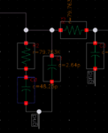
This is the loop filter I'm using

zzz.png

I am using ideal resistors and capacitors. Yes there is large oscillations at the loop filter output. Should I increase the final capacitance value?
 

FvM:
I simulated the PLL with same components except using an ideal oscillator from the library. The loop filter output after lock was perfectly constant. PFD input edges were matching perfectly. There were no spurs at the VCO output.

BigBoss.
This is the loop filter I'm using

View attachment 126325

I am using ideal resistors and capacitors. Yes there is large oscillations at the loop filter output. Should I increase the final capacitance value?
Your component values seem incorrect, pF level caps. are not usual PLL loop filter elements. Calculate them again with a proper calculator and try to do simulation.
 

My charge pump current is 2uA. So the capacitors are not large...
 

Status
Not open for further replies.

Part and Inventory Search

Welcome to EDABoard.com

Sponsor

Back
Top