E-design
Advanced Member level 5
I was testing some low-cost eBay switching power adapters and saw all had sloppy performance on step load testing.
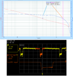
I opened it up and decided to test the gain/phase response at 500 mA.
Below is the plots from the FRA used. Looking at the first plot it can be seen why the response is so bad.
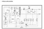
On further investigation, it appears that the manufacturer used such a massive value of roll-off capacitor without any testing or verification. On the application note of the flyback chip used in this, the capacitor (C4) value is for the designer to select and optimize. Since no value was indicated, someone thought that a 100 nF seemed like a good idea. The bigger the better, hey?
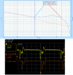
Reducing this to 10 nF made a good improvement in performance.
I opened it up and decided to test the gain/phase response at 500 mA.
Below is the plots from the FRA used. Looking at the first plot it can be seen why the response is so bad.
On further investigation, it appears that the manufacturer used such a massive value of roll-off capacitor without any testing or verification. On the application note of the flyback chip used in this, the capacitor (C4) value is for the designer to select and optimize. Since no value was indicated, someone thought that a 100 nF seemed like a good idea. The bigger the better, hey?
Reducing this to 10 nF made a good improvement in performance.
Attachments
Last edited: