Continue to Site

Welcome to EDAboard.com

Welcome to our site! EDAboard.com is an international Electronics Discussion Forum focused on EDA software, circuits, schematics, books, theory, papers, asic, pld, 8051, DSP, Network, RF, Analog Design, PCB, Service Manuals... and a whole lot more! To participate you need to register. Registration is free. Click here to register now.

IGBT modules + IR2110 + arduino

Status
Not open for further replies.

ricperes

Junior Member level 2
Joined
Feb 3, 2016
Messages
22
Helped
0
Reputation
0
Reaction score
0
Trophy points
1
Activity points
149
IR2110 driver + arduino

Hello , I have tried to control a full-bridge inverter. So i made my SPWM signals through Arduino like this code! I want to use a IR2110 driver, but I have seen many schematics to do this, I already use this : https://tahmidmc.blogspot.pt/2013/01/using-high-low-side-driver-ir2110-with.html , I used exactly the same values of C and R. In sum , you can give me a feedback , if this Schematic is good, or if my code is correct please? Thanks


Code:
void loop() {

  for (t = 0; t < 10; t = t + 0.001) {

    Uref = sin(2 * PI * 50 * t); // sin reference
    
    notref = -1 * sin(2 * PI * 50 * t); // negative sin reference
    
    carrier = ((2 / PI) * asin(sin(2 * PI * 3000 * t))); //triangular wave


    if (Uref >= carrier) {

      analogWrite(10, 0);
      delayMicroseconds(25);
      analogWrite(11, 255);
    } else {

      analogWrite(11, 0);
      delayMicroseconds(25);
      analogWrite(10, 255);
    }

    //********************************************//
    if (notref >= carrier) {
      analogWrite(3, 0);
      delayMicroseconds(25);
      analogWrite(9, 255);
    } else {
      analogWrite(9, 0);
      delayMicroseconds(25);
      analogWrite(3, 255);
    }
  }
}
 

Re: IR2110 driver + arduino

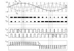
Hello, what i have tried to do is this:

f1.JPG-1230x0.jpg
https://e2e.ti.com/resized-image/__...erver-discussions-components-files/171/f1.JPG

So Uref and -Uref are the sinusoidal waves and the carrier is the triangular wave
 

Re: IR2110 driver + arduino

You did not informed exctly with which of those schematic were made your experiments.
Moreover, this piece of code do not make sense: You are getting the inverse of the same function, f-1(f(t)):

Code:
carrier = ((2 / PI) * asin(sin(2 * PI * 3000 * t))); //triangular wave

I'm not experienced in Arduino, but why don't you simply make something like this, instead ?

Code:
carrier = (2 / PI) * 3000 * t  ; //triangular wave

In addition, your code apparently put some value at the analog output of the Arduino board, buy in order to achieve your intent with the IR2110 driver, you should deal with some PWM output, digital of course.

- - - Updated - - -

Your original question concerned about the suited circuit for this task, and now you added an image that even answered my question.
 

Re: IR2110 driver + arduino

Sorry , but i don't understant .. you suggest to change the triangular wave
Code:
carrier = ((2 / PI) * asin(sin(2 * PI * 3000 * t)));
by this
Code:
carrier = (2 / PI) * 3000 * t  ;
... ?? This is a straight , i want a triangular wave... Sorry my confusion ...
 

Hello, i need some help please, What I do is create PWM signal on Arduino and through the IR2110 driver, control this IGBT module that is in the picture, I have tried to use this schematic but not sure I will give good results, someone tried it?

igbt.PNG

schematic.PNG
 

Re: IR2110 driver + arduino

Sorry , but i don't understant ...

You should be aware that the function y=arcsin(sin(x)) is the samething of y=x.

I have tried to use this schematic but not sure I will give good results, someone tried it?

Certainly, but as mentioned above, will not work with the code you posted above due to the reasons already mentioned, quoted below:

your code apparently put some value at the analog output of the Arduino board, but in order to achieve your intent with the IR2110 driver, you should deal with some PWM output, digital of course.

You have to replace the function analogWrite() by some API of Arduino which is able to generate PWM outputs.
 

Re: IR2110 driver + arduino

You should be aware that the function y=arcsin(sin(x)) is the samething of y=x.


Certainly, but as mentioned above, will not work with the code you posted above due to the reasons already mentioned, quoted below:


You have to replace the function analogWrite() by some API of Arduino which is able to generate PWM outputs.

I replaced the analogWrite by DigitalWrite. but you said that y=arcsin(sin(x)) is the samething of y=x., but when i plot a graphic in matlab for example, the results are different
 

Re: IR2110 driver + arduino

I replaced the analogWrite by DigitalWrite. but you said that y=arcsin(sin(x)) is the samething of y=x., but when i plot a graphic in matlab for example, the results are different

How different were the results ?
Which code you made for that simulation ?
 

Re: IR2110 driver + arduino

How different were the results ?
Which code you made for that simulation ?

Code:
void loop() {

  for (t = 0; t < 10; t = t + 0.001) {

    Uref = sin(2 * PI * 50 * t);

    notref = -1 * sin(2 * PI * 50 * t);

    carrier = ((2 / PI) * asin(sin(2 * PI * 10000 * t)));

    if (Uref >= carrier) {

      digitalWrite(10, LOW);
      delayMicroseconds(50);
      digitalWrite(11, HIGH);
    } else {

      digitalWrite(11, LOW);
      delayMicroseconds(50);
      digitalWrite(10, HIGH);
    }

    //********************************************//
    if (notref >= carrier) {

      digitalWrite(3, LOW);
      delayMicroseconds(50);
      digitalWrite(9, HIGH);
    } else {
      digitalWrite(9, LOW);
      delayMicroseconds(50);
      digitalWrite(3, HIGH);
    }
  }
}

just that , The first arm is ok! But the second arm not
 

Of course the results will be different. asin(x) is a multiple value function whereas matlab (I use octave) returns the principal value.

Your output will be a triangular wave. y=x and y=asin(sin(x)) are not really same.

Let us take a careful look. y=x is a straight line extended on both sides. It has a slope of 1.

sin(x) is both bounded above and below +/-1. asin(x) is having an infinite number of solutions but the principal value is bounded +/- pi/2. So we cannot have y outside +/-1. QED

Code is really simple but the language is tough.

thanks

So what is the best way to implement a SPWM in arduino?
 

Your output will be a triangular wave. y=x and y=asin(sin(x)) are not really same.

Let us take a careful look. y=x is a straight line extended on both sides. It has a slope of 1.

You are absolutely right, in fact y=x and y=asin(sin(x)) will not produce the same result, unless within the range [-PI/1...PI/2]. Anyway, the point I wished to emphasize is that the code is not optimized the fashion as it was made, and a lot of processing resource of the core may be wasted using the actual implementation arcsin(sin(. The function he wants to get is purely linear, and by using a simple logic could control the quadrant of the triangular waveform.
 

Status
Not open for further replies.

Similar threads

Part and Inventory Search

Welcome to EDABoard.com

Sponsor

Back
Top