Continue to Site

Welcome to EDAboard.com

Welcome to our site! EDAboard.com is an international Electronics Discussion Forum focused on EDA software, circuits, schematics, books, theory, papers, asic, pld, 8051, DSP, Network, RF, Analog Design, PCB, Service Manuals... and a whole lot more! To participate you need to register. Registration is free. Click here to register now.

Dual Modulus Fractional-N PLL

Status
Not open for further replies.

pancho_hideboo

Advanced Member level 5
Joined
Oct 21, 2006
Messages
2,847
Helped
767
Reputation
1,536
Reaction score
733
Trophy points
1,393
Location
Real Homeless
Activity points
17,490
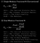
The averaged division ratio is calculated in the Fractional-N PLL feedback path like (1) of attached figure.
This scheme is well known.

However there is a different scheme like (2) of attached figure.

I don't know how to realize this scheme.

My questions are :

(a) What merit does this scheme have ?
A very fine frequency resolution with no residual frequency error ?
Enhanced randomnesss which can result in rare fractional spurious ?

(b) How to realize this scheme ?
Is there any document which can be helpful ?
 

Attachments

  • 160214-150525.png
    160214-150525.png
    34.8 KB · Views: 56

The first scheme gives whole integer division ratios, which is ideal for many practical purposes, and especially for phase locked loops at very high frequencies.

The modulus switching process completes each output cycle.

The second scheme is mixed fractional division, which produces long term jitter in the output. That is because the modulus switching is only completed over many output cycles.

Its like having an output cycle 10 units long followed by another cycle 10 units long then a third cycle 11 units long.

From this you then assume the averaged output is going to be 10.333333 units per cycle (31/3).
That may be true in one respect.
Or the jittery output may be unusable for many practical purposes.

If you have a constant 1000 Hz signal.
And every hundred seconds you add a narrow spike to that.
Is it really then 1000.01 Hz ?
 

Thanks for response.

The second scheme is mixed fractional division, which produces long term jitter in the output.
[.....]
From this you then assume the averaged output is going to be 10.333333 units per cycle (31/3).
That may be true in one respect.
Or the jittery output may be unusable for many practical purposes.
This scheme is adopted in actual products which are very high precision PLL.
https://www.analog.com/media/en/technical-documentation/data-sheets/ADF4355-2.pdf
 

It depends what it is for, and how you implement it.
High precision is not the problem.
The problem is phase noise and jitter.

There are other methods of getting very fine frequency resolution such as direct digital synthesis that may be much better for some applications.
 

Last edited:

If you have a constant 1000 Hz signal.
And every hundred seconds you add a narrow spike to that.
Is it really then 1000.01 Hz ?
I think the discussion is missing an important point. The fractional divider will be used in the feedback path. It's expected that the jitter can be mostly removed in the loop filter. Of course, this is only possible if the jitter period is short enough. We nee to look at the complete PLL to analyze the spurs generated by the fractional design.
 

It will always jitter if it uses direct fractional division.
The jitter comes for free with the technique.

However, a following phase locked loop with a very long time constant can greatly reduce this problem.
Again it depends on the application. If the required output is at hundreds of Mhz, a 10mS phase locked loop time constant might be considered pretty long.

If the required fractional division output frequency is at audio frequencies the jitter might be all but impossible to remove.
 

It will always jitter if it uses direct fractional division.
What do you mean by "direct fractional division" ?
I assume delta sigma modulation for realization of fractional division.

If the required output is at hundreds of Mhz, a 10mS phase locked loop time constant might be considered pretty long.
Fricker noise from devices are very large than such jitter and dominate phase noise characteristics for such very small offset frequency region.
 
Last edited:

The jitter is defined by the set division ratios, and their relationships. At some set frequencies the jitter may be negligible, at others severe.

Its obviously can be a useful technique, but its not a perfect solution by any means.

Many attempts at designing an HF fractional divider (3 to 30 Mhz) with steps of a few Hz have not been successful. And a great many people have tried.

It works much better at VHF and above.

At lower frequencies DDS is routinely used in a wide range of high end test equipment.
 

It will always jitter if it uses direct fractional division.
May be I misunderstood the question. I was referring to the question title which asks about fractional PLL rather than "direct fractional division". In an industry-standard fractional PLL, e.g. ADF4355 linked in post #3, the output is always derived from the VCO by a non-fractional divider.
 

The jitter is defined by the set division ratios, and their relationships.
At some set frequencies the jitter may be negligible, at others severe.
Its obviously can be a useful technique, but its not a perfect solution by any means.
Many attempts at designing an HF fractional divider (3 to 30 Mhz) with steps of a few Hz have not been successful.
Do you understand fractional-N PLL based on delta sigma modulation correctly ?

I don't mean fractional divider.
I mean fractional-N PLL.

Again back to beginning of this thread.
Scheme (2) is new technique.
I see scheme (2) first in ADI product.
 
Last edited:

You didn't show an actual PLL scheme, just described a fractional frequency divider without showing where it's placed in the loop. This might have brought up some misunderstandings.
 

You didn't show an actual PLL scheme, just described a fractional frequency divider without showing where it's placed in the loop.
If you know fractional-N PLL correctly, you can easily understand this equation, since this equation is very common in fractional-N PLL.

Fractional dividers are never used in fractional-N PLL.

Generally, Dual modulus prescaler or selection of phase from multi-phases scheme are used.
See "Similar Threads" of this thread.
 
Last edited:

Fractional dividers are never used in fractional-N PLL.
.
Dual modulus prescaler IS fractional division, although the fraction part must be fully completed within one output cycle to create a full integer overall division.

But a dual modulus prescaler with further modification to the modulus gating, can easily create two separate division ratios widely spaced over many output cycles.

All of this may or may not use a phase locked loop, its not mandatory.
Sometimes the output of a dual modulus divider is used directly.
 

Dual modulus prescaler IS fractional division
Not correct.
Dual modulus prescaler is no more than fixed divider, if it has no modulus controler.

Delta sigma modulator is a modulus controler.

Back to beginning of this thread.
We can easily realize scheme (1) by conventional delata-sigma modulator such as MASH-111.

On the other hand, how to realize scheme (2) ?

Sometimes the output of a dual modulus divider is used directly.
I don't think so from practical point of view.
It has bad duty ratio.
 
Last edited:

Divide by N counters are used all the time, and the dual modulus counter method is just another way of achieving that.

Duty ratio is not usually important for many frequency division applications, and for odd division ratios it is usually par for the course.

Plenty of frequency dividers out there that work fine without needing to have a phase locked loop.
 

Divide by N counters are used all the time, and the dual modulus counter method is just another way of achieving that.
Not correct.
If divide by N counters can operate at very high speed, we don't have to use dual modulus counter at all.

If very high speed multi-modulus-divider is required, phase selection(=changing) from multi-phases scheme is adopted.

Duty ratio is not usually important for many frequency division applications
I don't think so.
If duty ratio is not 50%, even order hamonics are included.
And if duty ratio is not 50%, we can not generate quadrature phase signals from it.

Plenty of frequency dividers out there that work fine without needing to have a phase locked loop.
I don't think so for current communication system which are both wireless and wired.
 
Last edited:

I feel a kind of purposeless fighting about a problem that's not related to the original question of this thread which is
Fractional-N PLL feedback path

First a comment about nomenclature. In my reading of popular PLL literature "dual modulus" isn't but a synonymous of "fractional-N" because modulus stands simply for the frequency divider factor. That's different from the terminology used in the post #1 link.

Secondly, a fractional divider with an interpolator of higher than first order generates a rather chaotic pattern, it's output signal might be not very different from the specific "dual fractional" design used by ADF4355. Respectively I'm unable to answer question a clearly. Higher frequency resolution seems to be obvious.
 

You are just being a pain.
Simply, your appends are all completely out of focus of the original question of this thread.

First a comment about nomenclature.
In my reading of popular PLL literature "dual modulus" isn't but a synonymous of "fractional-N" because modulus stands simply for the frequency divider factor.
That's different from the terminology used in the post #1 link.
Right.
I don't think title of this thread, "Dual Modulus Fractional-N PLL" is appropriate.

However, denominator of fractional number in fractional-N PLL is called as modulus.

Secondly,
...................................................
Respectively I'm unable to answer question a clearly.
Higher frequency resolution seems to be obvious.
I think scheme (2) must be a proprietary technique of ADI.
 
Last edited:

Status
Not open for further replies.

Part and Inventory Search

Welcome to EDABoard.com

Sponsor

Back
Top