Continue to Site

Welcome to EDAboard.com

Welcome to our site! EDAboard.com is an international Electronics Discussion Forum focused on EDA software, circuits, schematics, books, theory, papers, asic, pld, 8051, DSP, Network, RF, Analog Design, PCB, Service Manuals... and a whole lot more! To participate you need to register. Registration is free. Click here to register now.

[SOLVED] Wrong simulation results in Falstad

Status
Not open for further replies.

CataM

Advanced Member level 4
Joined
Dec 23, 2015
Messages
1,275
Helped
314
Reputation
628
Reaction score
312
Trophy points
83
Location
Madrid, Spain
Activity points
8,409
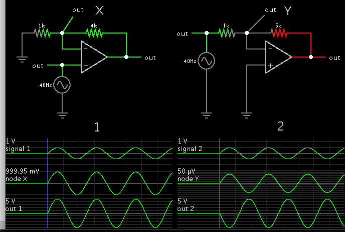
What is going on here?


The input is a simple sine wave with 1V amplitude.
 

Lefthand output is 6V, righthand 5V. Both schematics have a 5:1 feedback ratio (or so it appears).

I tend to think of the one formula (R2/R1) for the righthand situation. It's easy to remember. But there's another formula for the lefthand situation. Op amps are counter-intuitive that way.
 

The gain is correct(6 left one) but what about the phase of the output? Input=sine wave

Left circuit is a non-inverting one but the output is inverted ! When sine wave goes up, output should have gone up, but there goes down.

Right circuit(gain=-R2/R1) is an inverting one but it's output is not inverted ! When sine wave goes up, output should have gone down, but there goes up.
 
Last edited:

Falstad's AC source is ambiguous as to whether it is oriented upside-down or right side up.

You can tell by looking closely at the color of its wires. The upper wire appears red (negative) in both your schematics. Therefore the op amp inputs are working properly in regard to inverting or not inverting.

Most Falstad icons do not indicate the orientation of a component. I find it helps if I put an 'Analog output' at one lead, for a volt reading or scope trace. It's unambiguous.


Notice the snapshot was taken at a time when the source has a green upper wire, or positive waveform.
 
  • Like
Reactions: CataM

    CataM

    Points: 2
    Helpful Answer Positive Rating
Yes Brad you are right. I noticed that when trying to place a DC supply "Add voltage source 2 terminal (v)" that always appears placed upside down because I always drag the mouse to draw it from up to down and when I placed the AC source the 40 hz number did not appear in the wrong side and thought it is only for DC sources that they place it upside down.
 

Status
Not open for further replies.

Part and Inventory Search

Welcome to EDABoard.com

Sponsor

Back
Top