Continue to Site

Welcome to EDAboard.com

Welcome to our site! EDAboard.com is an international Electronics Discussion Forum focused on EDA software, circuits, schematics, books, theory, papers, asic, pld, 8051, DSP, Network, RF, Analog Design, PCB, Service Manuals... and a whole lot more! To participate you need to register. Registration is free. Click here to register now.

[SOLVED] Potentiometers not working properly in circuit

Status
Not open for further replies.

PramodMunaweera

Newbie level 3
Joined
Feb 12, 2016
Messages
4
Helped
0
Reputation
0
Reaction score
0
Trophy points
1
Activity points
33
Hi friends,

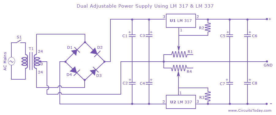
I built a dual variable power supply using LM317 and LM 337 as shown in the tutorial in the link below,

https://www.circuitstoday.com/dual-adjustable-power-supply-using-lm-317-lm337


but the problem with my circuit is the potentiometers used to adjust voltage not working and not changing the output voltage, i have changed the potentiometers and the problem is still there, when i connect different resistors instead of pots the circuit works fine, so the problem is with the pots.

Friends, please help me to solve this problem.Are there any typical problems with using pots in circuits.
 
Last edited by a moderator:

Are you sure that are using linear potentiometer instead of logaritmic ?
 

The 220 ohm resistors and 5k pots can be used with the more expensive LM117 and LM137 regulators. 120 ohms should be used with the LM317 and LM337, then the value of the pots should also be reduced.
The peak of the 24VAC is 34V and is reduced to 33V by the rectifiers. It will be higher with a low load current. The resistor and pots values shown will produce a maximum output of 30V, not 15V.

Make sure the pins on the ICs are correct. Also make sure you are using Name-Brand ICs, not cheap fake copies.
 

Check the voltage across R2 and R3 (both ends) with respect to ground and make sure the junctions of C1,C2; C3,C4; C5,C7; C6,C8 are connected to GND.
 

Yes I checked the potentiometers with multimeter

- Pramod -
 

make sure the junctions of C1,C2; C3,C4; C5,C7; C6,C8 are connected to GND as pointed out in #4.

Your schematic suggests that the junctions of the capacitors are not connected to the ground; why?
 

without load there will be full input voltage on output
No. Using 120 ohm in the voltage divider as mentioned by Audioguru will give sufficient load over the specified input and output voltage range. The originally chosen 220 ohm will also work in most cases, but could result in a too high unloaded output voltage for marginal chips. Nevertheless will 220 ohm still keep output voltage variability.

Being unable to change the output voltage at all suggests a much more basic fault like wrong chip connection, unconnected or defective potentiometer, defective or faked chip, etc.
 

Status
Not open for further replies.

Part and Inventory Search

Welcome to EDABoard.com

Sponsor

Back
Top