Continue to Site

Welcome to EDAboard.com

Welcome to our site! EDAboard.com is an international Electronics Discussion Forum focused on EDA software, circuits, schematics, books, theory, papers, asic, pld, 8051, DSP, Network, RF, Analog Design, PCB, Service Manuals... and a whole lot more! To participate you need to register. Registration is free. Click here to register now.

Strange diode biasing in upconverter mixer.

Status
Not open for further replies.

Terminator3

Advanced Member level 3
Joined
Feb 25, 2012
Messages
802
Helped
71
Reputation
142
Reaction score
63
Trophy points
1,308
Activity points
9,027
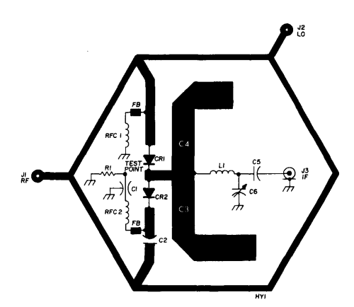
Here is well known design by S53MV:
http://lea.hamradio.si/~s53mv/zifssb/xband.html
where positive bias applied to diodes:
Since only positive bias is available through the 10kohm trimmers for mixer balancing, the BAT14-099R packages should be oriented correctly in the circuit. In particular, one of the two packages has to be installed upside down.

I recently found a design where biasing looks a little strange to me:


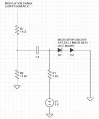
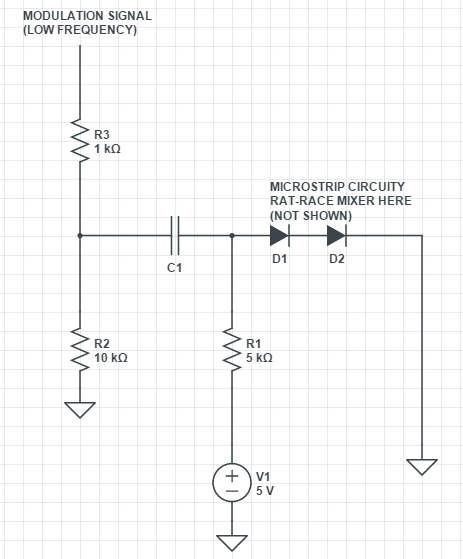
As i understand, R2 and R3 is a voltage divider. But it is placed before capacitor C1, so it does not affect diode biasing. Diodes are biased using +5V through R1 directly, without voltage divider.
R2, R3 and C1 does not look like low pass filtering. Can anyone explain purpose of R2 and R3?
 
Last edited by a moderator:

Additional question about DC return path:
https://www.qsl.net/yo4hfu/Files/TG/RAT RACE 1296 mixer.pdf
https://www.qsl.net/va3iul/RF Mixers/RF_Mixers.pdf


30_1300274007.jpg

(https://www.edaboard.com/threads/205910/)
In a single-balanced diode Mixer it is essential that the DC path through the diodes to
be continuous. If the diodes are open-circuited at DC, the Mixer it will not work.
Often, the hybrid provides that continuous path.

I can't understand how to trace DC return path around rat-race mixer. It is easy on the first image, but difficult for the second one. There is "LOWER LOSS" stub with via on the second image. Can we make SUM or delta port grounded at DC with thin line + quarterwave open stub to GND? Or even choose arbitrary position on rat race circle and put thin line + quarterwave radial stub to GND.

If we use separate diodes, DC return path is made pretty obvious. Can someone explain DC return path for series diodes when used in rat race mixers?
 

* R2 may be there to provide a current path for C1 to discharge, and return to some default state.

* The two series diodes raise the middle node to a certain volt level. The incoming signal causes that voltage to rise and fall a little in response. Then the node returns to the previous volt level. (Is output taken from that node? Just a guess.)

I have no experience with a rat-race mixer, so I could be wrong.
 
Thank you for your answer. In the mixer i found output is taken from the point between two schottky diodes (connected in series in single 3-pin package, rectangle on a "Figure 5" image.)
 

r3 is probably there to keep the rf diodes from blowing out. like maybe they are driving R3 with a digital gate, and they do not want the full 5 Volt spike to get thru the capacitor to the diodes as the gate changes output state. R2 is probably not needed, but might help discharging the capacitor in time for the next bit of data to get thru the capacitor.
 
Interesting, i checked control board. Diode is driven by DSP DAC output through an OpAmp. Although opamp output never exceeded 1v in amplitude on oscilloscope, it is 5V-powered OpAmp, so your explanation seems to be right.
 

sometimes when you first turn on the power supply, an opamp will peg to the +5 rail momentarily. Maybe they were burning out diodes and needed to add it. Or maybe it is just superfluous.
 
Status
Not open for further replies.

Part and Inventory Search

Welcome to EDABoard.com

Sponsor

Back
Top