Continue to Site

Welcome to EDAboard.com

Welcome to our site! EDAboard.com is an international Electronics Discussion Forum focused on EDA software, circuits, schematics, books, theory, papers, asic, pld, 8051, DSP, Network, RF, Analog Design, PCB, Service Manuals... and a whole lot more! To participate you need to register. Registration is free. Click here to register now.

What are the differences between wave generator and oscillator? (Specific design)

Status
Not open for further replies.

itayd100

Junior Member level 3
Joined
Jan 7, 2016
Messages
29
Helped
0
Reputation
0
Reaction score
0
Trophy points
1
Activity points
233
Hello,

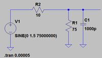
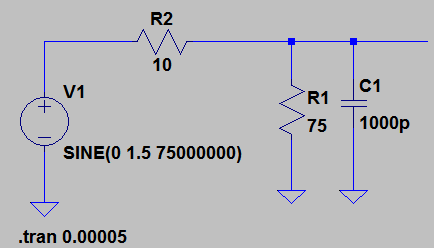
I design the attached circuit:
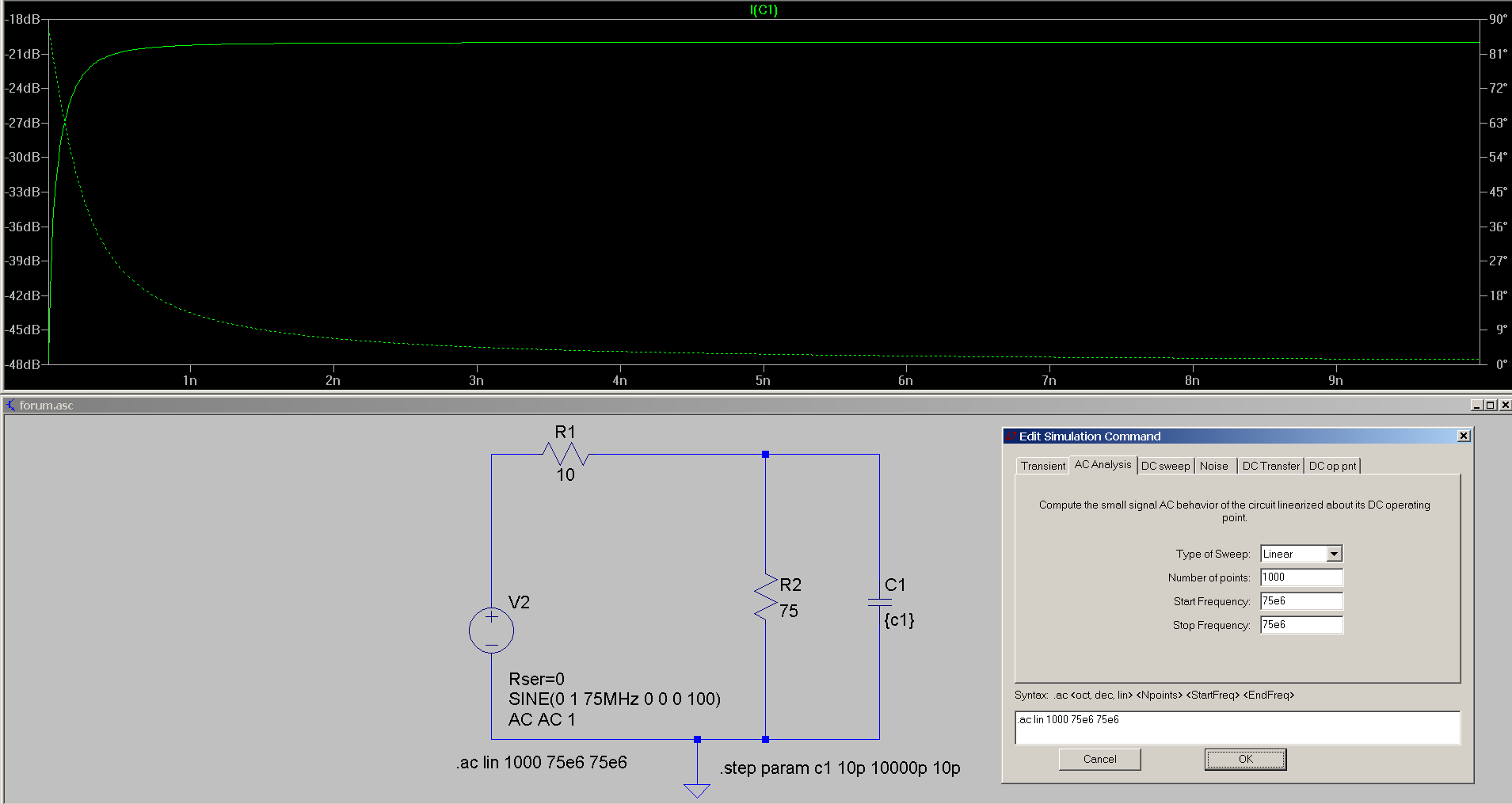
75 MHz Sine wave that connected to R and C in parallel


The output, the amplitude of the sine wave, is changing according to the C, more capacitance smaller amplitude of the sine wave.

When I tried that in the lab I got 2 results:
1. When I connected the signal generator as an oscillator I got the same results - higher C lower amplitude (of the sine wave in the output)
2. When I connected it to oscillator (https://www.farnell.com/datasheets/75480.pdf) I'm getting different result: the output is a sine wave, but if I make C higher the amplitude becoming lower until the sine wave (in the output) is "flipping" (kind of changing phase) and, if I keeping the C higher, the sine wave in the output getting higher

What are the differences between the two?
How can I make the oscillator work like the wave generator in this case?
 

Your oscillator appears to be an HCMOS device and will be sensitive to loading. The datasheet you provided specifies a maximum capacitive load of 15pF. You have an impedance matching problem. Your signal generator is probably a better match due to lower output impedance than the oscillator, which has a relatively high output impedance. If you are changing the capacitance value, you should expect to see a change in phase and magnitude. It looks like you are using LTSpice, so use the AC analysis to see how the changing capacitance affects the phase and magnitude.
 
Last edited:
Thanks for the answer.

I know hot to change the frequency while running (in the AC analysis), but I don't know how to change the value of a capacitor while running. How can I do that?
"You have an impedance matching problem" - buffer should be the solution? If yes, what kind of buffer will be good?
 

The output, the amplitude of the sine wave, is changing according to the C, more capacitance smaller amplitude of the sine wave.

When I tried that in the lab I got 2 results:
1. When I connected the signal generator as an oscillator I got the same results - higher C lower amplitude (of the sine wave in the output)
2. When I connected it to oscillator (https://www.farnell.com/datasheets/75480.pdf) I'm getting different result: the output is a sine wave, but if I make C higher the amplitude becoming lower until the sine wave (in the output) is "flipping" (kind of changing phase) and, if I keeping the C higher, the sine wave in the output getting higher

1. The C1 is in the output load and shorts the voltage. This is acting like a bypass capacitor - the higher the frequency, the lower the impedance and larger is the reduction.

2. This is called resonance. The oscillator you are using is having a capacitive output- this is common. This capacitor is part of the voltage source. Together with R2 and C1, it is having a natural frequency with some Q value. As you sweep the frequency, you cross over the resonance point, the phase gets inverted and the oscillator dumps more energy into the output cap.
 
Hey c_mirta,

I'm not changing the frequency - the frequency is always the same (75Mhz), C1 is the only value that changing.
I'm trying to get the same result that I got with the function generator (1) with the HCMOS oscillator (2). Do you have any idea how?
 

A HCMOS crystal oscillator is designed to drive digital circuits with high input impedance. It's rather intended to drive low R/high C loads, nor to achieve specific "analog" waveforms.
 

1000pF with a 10R will give you a time constant of 10000 ps or 10 ns. In terms of frequency this is around 100 MHz.

As you increase C1, the time constant will increase and the low pass filter phase shift will increase. When you increase the C1 to 2000pF, the phase shift has become more than 180 degree. It looks that the wave has suddenly flipped over. With C1 equal to 2000pF, the frequency is around 50MHz and the system has crossed the resonance point.

A simulation is the best way to view the phase shift and the change in amplitude and if you increase the C1 value still further the amplitude will again decrease.
 
Last edited:

I know hot to change the frequency while running (in the AC analysis), but I don't know how to change the value of a capacitor while running. How can I do that?
"You have an impedance matching problem" - buffer should be the solution? If yes, what kind of buffer will be good?

I do not believe that you can sweep a component value with the AC Analysis in LTSpice, but you can set the start and finish frequencies to 75MHz and rapidly acquire data points for plotting in a spreadsheet by alternately editing the capacitor value in the schematic, running the AC analysis, and cutting and pasting from the tabular data.

As to a buffer amp, this is an opportunity for you to design your own. The component library of LTSpice has a number of JFETs (njf) with low gate capacitance. I suggest that you select a JFET from those that are available, familiarize yourself with the datasheet, and Google "JFET amplifier." You will find a large number of examples that will get you started.
 
I'm mostly using this syntax
Code:
.STEP PARAM <param> LIST <value list>
 
I'm trying to get the same result that I got with the function generator (1) with the HCMOS oscillator (2). Do you have any idea how?

An ideal function generator has ZERO internal impedance. Unfortunately we do not have ideal function generators. Usually they will tell that the source is so much OHM in parallel with so much pF. At 75MHz source impedance is not negligible.

For an oscillator, similar but different specifications will be there. Both capacitance and resistance will be specified and they will be different from that of a function generator.

There will be no more difference from the simulation point of view. Unfortunately I do not know how to simulate (true).
 
Last edited:

Status
Not open for further replies.

Similar threads

Part and Inventory Search

Welcome to EDABoard.com

Sponsor

Back
Top