Continue to Site

Welcome to EDAboard.com

Welcome to our site! EDAboard.com is an international Electronics Discussion Forum focused on EDA software, circuits, schematics, books, theory, papers, asic, pld, 8051, DSP, Network, RF, Analog Design, PCB, Service Manuals... and a whole lot more! To participate you need to register. Registration is free. Click here to register now.

Compensator design for Boost pfc recifiers

Status
Not open for further replies.

biswaIITH

Full Member level 4
Joined
Aug 23, 2014
Messages
204
Helped
27
Reputation
54
Reaction score
28
Trophy points
1,308
Location
Hyderabad
Activity points
2,907
I am designing one 1 kW boost pfc rectifiers.I am planning to use average current mode control(ACMCs).In stead of using dedicated Average current mode ICs ,can we achieve ACMC using opamps i.e. can we design the entire feedback circuit using opamps ,error amp etc..If yes can someone suggest me any book or source from where i can learn about the compensator design to be used in the feedback circuit for the same..
 

yes, just see the opamp circuit shown in the lt1248 datasheet..
http://cds.linear.com/docs/en/datasheet/1248fd.pdf

I appreciate you use average current mode control, because with current mode control , ccm pfc circuit would need very large amount of slope compensation for when voltage is near zero crossing...so average current mode control is common for pfc's
 

can we design the entire feedback circuit using opamps

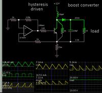
I don't know if this simulation is of any use, but I devised a way to make a boost converter hysteresis driven via a single op amp.

The sense resistor is common to both halves of the cycle.


It's tricky to adjust properly. Values need to cooperate or else the system stagnates. I've tried configurations with more op amps and I think that would make it easier to adjust.
What is this software you are using for simulation???
 

You can certainly due a ACM feedback loop with discrete components. If you want to make a completely DIY PFC controller, the more challenging part will be the multiplier which generates the reference to the ACM control loop.
 

Indeed, and I wonder really, would a microprocessor and software really be needed to get the multiplier done properly. I mean, there are analog multiplier chips available from Analog devices etc, but I think it would be tricky.
 

I am trying to simulate a boost converter PFC in matlab/simulink with the following specification

Input supply voltage=230vrms
output load=250watt
output voltage=400v
But i am getting distorted waveforms which is confusing..Below is the attached document.Can someone help me out??
 

Attachments

  • Simulation Results.pdf
    426.3 KB · Views: 83

I would do it bit by bit.

Start by attaching a decent load , preferably a voltage source load of 400v so that you dont keep overvoltaging the output.

Ok, i presume you are doing CCM PFC.

Then get it going open loop into that load...just concentrate at first at getting the sinusoidal envelope of current into that load...following the mains voltage sine.

So get your current sense reference voltage to vary sinusoidally in tandem with the mains voltage sine.....(or rather, the rectified mains voltage sine, as you dont want a negative current sense reference voltage).

Then see what power your sim is driving into the load.....it'll probably not be right as your open loop.

Now do you see what you have to do?

...to go further, you have to put on a resistive load, and try and regulate it to 400v. (or therabouts)

...so that sinusoidally varying sense resistor voltage needs itself to vary in its peak value.......How do you do that...well you have already made it "match" the shape of the voltage sine by using some function, probably a multiplier.

So now you bring in that one other value that we havent spoken of yet...the error amplifier voltage...the bigger the error amp voltage , the lower you are below 400v, and the more gain you want to give to the half wave sine reference voltage....and remember , the mains is only 50hz, so do all your gain changing and stuff really slowly, say at 10hz....

.....so , just mess with the gains that you apply to the error amplifier voltage, and to the sensed mains voltage sine, and always vary the sense resistor voltage as a 100hz half sine, but bit by bit, vary the peak of this sine, so that you eventually get into regulation
 

I have not divided the square of the input voltage in the multiplier ckt as done in uc3854.Do u think it is making the input current distorted??And one more thing how to find the optimized value of gain K, and Kp Ki values of both the controller???
 

Well, all i can say is it looks like you are trying to do it all at once. Try first to get a sinusoidal current envelope in your boost pfc inductor.
Yes I think there is something about squaring the input voltage, but you can add that in by trial and error when you have got the sinusoidal current envelope shape right.
I would find the k values by trial and error....I suppose you start low and build up.

- - - Updated - - -

I believe when you have got sinusoidal envelope inductor current, you will see how to move on from there.
 

Status
Not open for further replies.

Similar threads

Part and Inventory Search

Welcome to EDABoard.com

Sponsor

Back
Top