Continue to Site

Welcome to EDAboard.com

Welcome to our site! EDAboard.com is an international Electronics Discussion Forum focused on EDA software, circuits, schematics, books, theory, papers, asic, pld, 8051, DSP, Network, RF, Analog Design, PCB, Service Manuals... and a whole lot more! To participate you need to register. Registration is free. Click here to register now.

smps board burn problem

Status
Not open for further replies.

5282

Junior Member level 2
Joined
Dec 5, 2015
Messages
21
Helped
0
Reputation
0
Reaction score
0
Trophy points
1
Activity points
160
hiii
i use ic 3842 as smps controller
but i try about 30 days and i can't solve problem :sad:

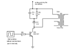
the problem is the power transistor driver is always burn and i try every thing and it's burn in less than 1second.
 

Hi,

How can we help. With your given information it is impossible.

Show your complete schematic. Give additional informations
Show your PCB layout. At least photos.

Show scope pictures, if you have.

Give a detailed descriptin of the failure.

What have you done so far to debug?

Klaus
 

I wish I had a dollar or an euro every time someone comes with a "my circuit does not work", but fails to provide any meaningful information.

All I can say at this point of time, in my previous company, which at one point was the world's largest power supply company, we used the 3842 everywhere. We literally used millions of those devices a year. It has its own idiosyncrasies like any IC, but it is relatively straightforward to use and very reliable.
 
  • Like
Reactions: KlausST

    KlausST

    Points: 2
    Helpful Answer Positive Rating
thank to all i burn about 16 transistor :-x and 6 mosfet :-(

666.png

the transistor is burn in less than 1 second when i test it with 220v.
but the circuit work well when i work only with 24v :popcorn: .

i use current limiter when i work with the main power 220v "40w lamp as resistor"
i powered the 3842 by 24v "external power source"
i use about 100 turn primary when i work with 220v.
 
Last edited:

Without a load, high flyback Vce can easily kill the transistor. The snubber is only good to absorb the leakage inductance energy, not the full flyback energy. The other point is that the 1K base resistor value will put the transistor into linear operation with huge losses.

I don't know which test is intended with this circuit, but it should consider the transistor's safe operation area. Definitely no "3842 problem".
 

thank you i was think the snubber circuit for high flyback Vce.
but when i work with 220v it act as short circuit are this duty cycle problem. and with 24v it work well.
 

Hi,

Please check with your gnd of ic, the primary gnd and secondary gnd should be isolated!

Bill Lee
 

thank you i was think the snubber circuit for high flyback Vce.
but when i work with 220v it act as short circuit are this duty cycle problem. and with 24v it work well.

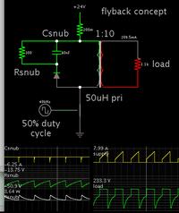
From my experimental simulations, you need a larger capacitor and smaller resistance. The snubber capacitor must absorb an energy spike quickly, and the resistor must dissipate it gradually.

My simulation is only a rough match to your setup. It's to show how the DCR snubber acts.


The load gets 40W.

Notice that voltage on the capacitor is kept within a manageable range. The resistor dissipates peak power of 8.64W.
 

Without any feedback, how do control the duty cycle?
Do you realize that the 3842 is a current mode controller, and that the peak switch current is controlled that way?
 

Status
Not open for further replies.

Similar threads

Part and Inventory Search

Welcome to EDABoard.com

Sponsor

Back
Top