Continue to Site

Welcome to EDAboard.com

Welcome to our site! EDAboard.com is an international Electronics Discussion Forum focused on EDA software, circuits, schematics, books, theory, papers, asic, pld, 8051, DSP, Network, RF, Analog Design, PCB, Service Manuals... and a whole lot more! To participate you need to register. Registration is free. Click here to register now.

What is the principle of 8753's test port coupler?

Status
Not open for further replies.

heqinlong

Newbie level 2
Joined
Jan 5, 2016
Messages
2
Helped
0
Reputation
0
Reaction score
0
Trophy points
1
Activity points
13
I am very confused about the coupler in 8753E/ES。
I found the pics in this site:
http://www.union-rnd.com/8753e8753es%E5%86%85%E7%9A%84%E8%80%A6%E5%90%88%E5%99%A808753_60365%E6%8B%86%E8%A7%A3/
I also have the schematic diagram of 8753A/C's coupler:
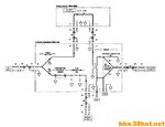
160845pvt4y6vmm98qw7i1.jpg
they are so different.
What is the principle of 8753's test port coupler?
 

Part of the sweep input goes to the instrument, part goes to a RF bridge which has a precision termination inside and a test port to the outside world. The unbalance output from the bridge goes to the instrument.
So if you use the sweep as your horizontal time base, then if you have a good match on the test port, the output would be low right across the swept frequency for your vertical deflection. If the test port was open circuit then the output would be high across the swept frequency. The attenuator allows the scale to be calibrated. If some other circuit was connected to the test port then the display would show humps and troughs. If the instrument can measure the phase of the two RF sources then the exact impedance (C or L) could be found or a Smith chart displayed.
Frank

I know this basic theory. I want to know the principle of 08753-60365.Forgive of having little talent and less learning,I am so puzzled about this coupler.:bang::bang:
 

Status
Not open for further replies.

Part and Inventory Search

Welcome to EDABoard.com

Sponsor

Back
Top