Continue to Site

Welcome to EDAboard.com

Welcome to our site! EDAboard.com is an international Electronics Discussion Forum focused on EDA software, circuits, schematics, books, theory, papers, asic, pld, 8051, DSP, Network, RF, Analog Design, PCB, Service Manuals... and a whole lot more! To participate you need to register. Registration is free. Click here to register now.

Battery charging circuit using LM2576T and LM2576S 5.0 fixed

Status
Not open for further replies.

SiddharthGajjar

Junior Member level 3
Joined
Jan 6, 2016
Messages
31
Helped
0
Reputation
0
Reaction score
0
Trophy points
6
Activity points
289
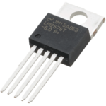
we have 10000 mAh xiomi power bank. and we had implement a circuit of LM2576(fix) 5.0 fixed output from datasheet

our input voltage is 12V 1 A DC adapter.
ss34 schottky diode input capacitance is 470uF/25V and output capacitor is 1000uF/25V
and 220uH inductor.

20111013234141224.jpg

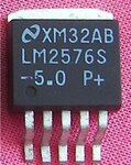
Now when i plugged my LM2576T 5.0 through hole ic on breadboard and i checked the voltage is 5.05 V dc and charging current towards battery is 1.5A. now in same circuit i am replacing my LM2576T with LM2576S 5.0 fixed output (only difference is LM2576T is through hole and LM2576S is SMD)

here problem arise, it gives me 5.05 volt DC but shows 0 current when attached with my battery bank...: sad:

so what is the problem pls suggest me.
 

Try to do load regulation test on the both the regulators. It will give you the fair idea at the point where the problem occurs..
 

Since the input current to the power bank is correct but the current is zero then either the polarity is backwards or the power bank is already fully charged.
 

I don't see any batteries, charges and e.t.c. here. Hi trying to build a DC/DC converter. And if the schematic based on datasheet doens't work, that means that something goes wrong with his h/w, wich is not shown. So, basicaly, we can't help.
 

I don't see any batteries, charges and e.t.c. here.
He said he is using the 5V power supply to charge a "power bank".
A power bank is a charging circuit that has an input of 5V to charge a lithium battery cell and the cell drives a voltage stepup circuit that produces an output of 5V to charge a cell phone.
When the battery cell in the power bank is fully charged then it disconnects the battery so then it draws no more current.
 

Have you connected the 4th PIN of 2576 to the out put? (Feed back PIN). for fixed regulators, the Feedback pin must tied to the output.
 

i am getting the actual ouput voltage and current as i want with through hole LM2576T ic

lm2576t-5.0.png

in same circuit when i replace the ic with its SMD version LM2576S it doesn't give me output like throgh whole version
Sell_U2010B,TDA2030,NJM2561,LM2576,LM2596,LTC3200,LTC3202,2SC3356,LM2576S-5.0,LM2576S-3.3,LM2576.jpg
 

Status
Not open for further replies.

Similar threads

Part and Inventory Search

Welcome to EDABoard.com

Sponsor

Back
Top