Continue to Site

Welcome to EDAboard.com

Welcome to our site! EDAboard.com is an international Electronics Discussion Forum focused on EDA software, circuits, schematics, books, theory, papers, asic, pld, 8051, DSP, Network, RF, Analog Design, PCB, Service Manuals... and a whole lot more! To participate you need to register. Registration is free. Click here to register now.

Astable Multivibrator using Transistors

Status
Not open for further replies.

wfg42438

Member level 3
Joined
Jun 29, 2015
Messages
54
Helped
0
Reputation
0
Reaction score
0
Trophy points
6
Location
California
Activity points
620
Hello,

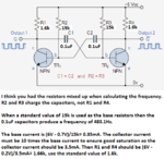
Can someone please explain how to go about choosing the collector resistors for this topology?

Say i want frequency of 500 Hz, then i know that :
If i let C1=C2=0.1uF then i find that R1=R4=14.5k
will provide the needed frequency

For some reason i dont know how to Choose R2=R3

If VCC=5V and VCE=0.3 V (to ensure im in the active region) then VR2=4.7V but how do i determine Ic to choose R2?

Can someone please help out?

These variables are based on the following Diagram

**broken link removed**
 
Last edited by a moderator:

The frequency is dependent on Vcc and these designs are supposed to be educative. You should use a 555 or some inverter gates. These circuits are are very good for flashers and similar designs.
 

With an Rb of 15K, you need to make sure that the transistor just goes into saturation. So (Vcc-.8)/15K = Ib. therefore Ic = Hfe X Ib, so Rc =(Vcc-.3)X 15K/ Hfe X (Vcc-.8) or ~ 15K/Hfe. 1K would do.
Frank
But most transistors do not saturate if their base to collector current is defined by hFE. HFE is used for a transistor that is linear and is NOT saturated. An ordinary 2N2222 is far from saturation (Vce of 10V) when its collector current is Ib x hFE. The base current is spec'd at 1/10th the collector current for it and most other little transistors to be saturated.
 
My apologies about the link, please see the diagram below:

tim20.gif
 

Why do we want the transistor to operate in the saturation region and not in the active region?

I figured the main objective was to Bias the transistor, where Vbe=0.7 V and 0.2 V<Vce<Vcc, and we choose a collector current to work with?

For example say we choose Ic=1mA then R1=R4 would be found as follows:

Ic= Vcc-Vc/R1 which means we can solve for R1, is this at all close to right?

If so how can i go about choosing an appropriate Ic??
 

I don't understand what's your problem with saturation in this circuit. The astable multivibrator is designed to work in saturation. That's at least a practical requirement because transistors have temperature and type dependent current gain, but the circuit is supposed to work under all conditions. The base resistors can be e.g. selected to work with minimal current gain at the saturation limited, thus the circuit is in saturation for higher current gain values.
 

Why do we want the transistor to operate in the saturation region and not in the active region?

It is good to operate in the saturation region because the transistor works as a switch under such conditions. It is just turned off and on by the gate voltage.

If you choose the R1 and R3 values carefully, the switching will be fast and will not depend critically on the transistor parameters.

If you want to use them to work in the active region, the circuit will not work well if you change the voltage or the resistors...
 

You calculated the frequency with the wrong resistors. I fixed it:

Yes you are correct i was referring to the wrong resistors, thank you for pointing that out

I looked over what you posted and for VCC=5V, VBE=0.7V, VCE=0.2 and Ic=10Ib C=0.1uF i found what is seen in the excel screen shot (Please note all current calculations were done using STD value resistors)

Can you please tell me why Ic=10*Ib is that simply a rule of thumb when using a BJT in saturation?

Now when i went to simulate this i noticed that i dont get perfect square pulses. I end up with Shark fin like pulses, do you know why?

I was curious what would change if Rc was decreased so i brought it down to 1k and i saw that as we increase Ic i get closer to an ideal square pulse

500A.PNG500B.PNG500c.PNG
 

If both the transistors are exactly identical (and the circuit is symmetrical), it won't work. The pulses are not square because the voltage is the capacitance charging curve. If you run the same circuit at 15V, the curves will be more 'square' looking (they will still be the capacitor charging curves). You can assume Ic=20*Ib and it will still work. The junction transistors are current driven devices and the gain (dc small signal) is usually less than 100. If you take Ic=10*Ib, you are confident that the transistor will be driven hard into saturation.

I do not know why you call them shark fins?
 

A transistor without negative feedback is very non-linear, especially as it approaches cutoff. Look at the distortion of this sinewave that is causing some of your "shark fins":
 

Attachments

  • transistor distortion 4.png
    transistor distortion 4.png
    22.7 KB · Views: 55

If you remove C3 and R6 (they are the real loads on the Q1 collector) how would the simulation look like? The simulation circuit is without feedback, true, but with only 35mV modulation is working in the linear region (I presume) because you are feeding only 12uA into the base. The output is reaching close to 12V (minus a diode drop) and is close to getting clipped.
 

If you remove C3 and R6 (they are the real loads on the Q1 collector) how would the simulation look like? The simulation circuit is without feedback, true, but with only 35mV modulation is working in the linear region (I presume) because you are feeding only 12uA into the base. The output is reaching close to 12V (minus a diode drop) and is close to getting clipped.
Actually, the transistors are switching on and off, they are never linear.
Each capacitor is charged by the collector resistor of the transistor that is turned off so of course it shows the curve of a charging capacitor. The base resistor of the transistor that is turned off discharges the capacitor.

I think the waveform will be "more square" if very high gain transistors (darlingtons?) are used with high value base resistors. Then the capacitor values can be smaller so they are charged faster by the collector resistors.
 

Status
Not open for further replies.

Part and Inventory Search

Welcome to EDABoard.com

Sponsor

Back
Top