Continue to Site

Welcome to EDAboard.com

Welcome to our site! EDAboard.com is an international Electronics Discussion Forum focused on EDA software, circuits, schematics, books, theory, papers, asic, pld, 8051, DSP, Network, RF, Analog Design, PCB, Service Manuals... and a whole lot more! To participate you need to register. Registration is free. Click here to register now.

[SOLVED] LM 317 for SIM900 will it work? .... need some suggetions

Status
Not open for further replies.

SiddharthGajjar

Junior Member level 3
Joined
Jan 6, 2016
Messages
31
Helped
0
Reputation
0
Reaction score
0
Trophy points
6
Activity points
289
hey
i am planning to use LM317 as power supply for SIM900 to get 4.2 regulated output voltage...

will this work????

regards
 

Hi,

It is not a qestion of devices.

It is a question of voltagees, currents and power dissipation.
So give us those values.

Now we can only say:
Yes, it is possible to generate 4.2V with an LM317.

But uf you want to draw 10A, or your input voltage is 230V AC, we have to say: No.

Klaus
 

My input voltage is 5V DC
burst current for SIM900 is 2A
after that my application on SIM900 takes 40mA constant.

so using LM317 with sim900, would it be reliable???
 

Hi,

Did you read the datasheet? --> LM317 is specified for only 1.5A.

****
5V input and 4.2V output with 2A max current. This means the dropout voltage of the regulator must be less than 0.8V.
Expect a dropout voltage at the LM317 of at least 1.5V (see chart "dropout voltage" in datasheet).

So the LM317 Can neither deliver the current , nor deliver the voltage. It is not suitable.

***
Hints:
You say 5V input voltage. Be careful with that. Often supplies go diwn with voltage when you draw current. Therefore you need to know the lowest possible voltage (input to your regulator) with full load. 2A in your case.

Power dissipation.
Ptot = (Uin- Uout) × I. In your case (5.0V - 4.2V) × 2 A = 1.6W. Even a big LM317 package (TO220) has a thermar resistance (junction to ambient) of 50K/W. 1.6W x 50K/W gives 80K of temperature rise. With an ambuent temperature of 30°C this means 110°C.
Therefore i recommend to use a heat sink.

Please use interactive part search engines at vendors or manufacturers to find a suitable device.
Look for special "low dropout regulators" = LDO.

Klaus
 
Re: LM 317 for SIM900 will it work? .... need some suggestions

My input voltage is 5V DC
burst current for SIM900 is 2A
after that my application on SIM900 takes 40mA constant.

so using LM317 with sim900, would it be reliable???

I think the 0.577ms 2A current burst in a 4.615ms period with otherwise 40mA consumption can be supported by a big cap: a capacitance of ≧ 1.5mF is sufficient to prevent a voltage drop from 4.2V down to below 3.4V (minimum supply voltage of the SIM900).

Another choice would be a single small 3.6 .. 4.2V Li-Ion accumulator cell, as suggested by the SIM900 data-sheet.

The mean current (<300mA) can be provided by an LM317 .

See also this thread.
 
A 3A regular (not Schottky) silicon diode, such as an 1N540X (X= 1, 2, 4, 6 , or 8), in series with the 5V will drop about .7V @ 40mA to 0.84V @ 2A giving an output voltage of about 4.3V to 4.1V.

This spec says the SIM900 can operate over a voltage range of 3.2V to 4.8V so that would seem acceptable.

For less drop you could use a Schottky diode. For example the 2A SS24 will drop about .25V @ 40ma and 0.5V @ 2A.
 
Last edited:

The problem with a diode may be an overvoltage condition with very low load, as well as significantly larger drop (loss of regulation) on maximum load.

The really elegant solution would be to use a low-dropout regulator ("LDO") to reduce the voltage from 5v to 4.2V. However, the "5V" is not always 5V, as tehre will be some load-dependent drop in addition to the general tolerances (may be easily +/-5% ).

Even resistive losses at the peak current moment should be considered, especially if there is any significant wiring in between the power supply and load.

One possible professional-quality LDO is Texas Instruments TPS75201QPW, which has maximum drop-out voltage of 400 mV at 2 A, and has a good load-current transient handling ability. It comes in a SSOP-style package with 0,65 mm pitch, so it should still be possible even to mount with "home-grade"equipment (but is not an easy piece for inexperienced constructors!).

However, there are very many supplies and types of LDOs with low drop-out and 2A capability. Just look at manufacturers' such as TI, selection web pages, or use for example DigiKey's selection system for sorting out which ones to look closer!
 

Conversion of 5V to 4.2V at 2 Amps rating using LM317 is not a solution for your problem. Better look for another regulator
 
The problem with a diode may be an overvoltage condition with very low load, as well as significantly larger drop (loss of regulation) on maximum load.
..................
Yes, that "may" be a problem.
But if diodes are used similar to the ones I mentioned, than the voltage drops should also be similar (and well within the limits of the load).
 

My GSM modem continuosly transmitting garbage value...
what is the reason

i was testing it in range of 3.2 volt to 4.45 volt range.....
with lm317 regulator attached with 5V input voltage 1000uF/25vfor both iput and outut capacitance

adjust and output pins are short to get 4.45 vtg.

is it damaged or what????
 

Hi,

My GSM modem continuosly transmitting garbage value...

I wonder how you know this....
And I wonder why you think this is caused by the power supply.
There are hundreds of other possible causes.

Please describe:
Connected hardware, (schematic)
Modem setup
To the modem sent data, with timing and modem feedback data
Expected data from the modem to be sent
Real data sent by the modem

Klaus
 

Before the modem connects to the GSM network (e.g. before attaching a SIM card and entering a valid SIM PIN), it won't consume high current. If you have already communication problems in the early phase, it's unlikely related to GSM burst current, rather a trivial UART wiring problem.
 

How are you reading the transmitted data of GSM. If there is an error while reading that you may get garbage values. Mainly check for the function whether it is happening or not?

Post your circuit & convey your application to suggest you better ideas
 

i checked that on UART sir. when the voltage nearby 3.4 V.

when voltage manually set 4.45V from variable source it work perfect.

SiddharthGajjar
 

Sounds like a interface problem with whatever you have connected as a terminal then. At lower voltage it probably isn't meeting the logic levels it expects. Show us what you are using to talk to your module.

Brian.
 

i was testing it in range of 3.2 volt to 4.45 volt range.....
with lm317 regulator attached with 5V input voltage,
adjust and output pins are short to get 4.45 vtg.
You did not read the datasheet for the LM317:
1) The ADJ and OUT pins are NEVER connected together.
2) The input must be at least 2.5V higher than the output (it is called the dropout voltage) when the load is 1.5A.
 

yes you were right the voltage level wasn't meeting the logic levels... i connect the terminal FTDI with input of LM317 and it is now working..

- - - Updated - - -

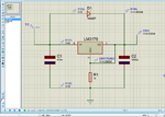
this diagram works in simulation as well as practically without any heat nor fluctuation.

LM317_PS_SIM900.png

i am getting 4.33 Vdc and it can feed burst current too.

now i will use this for SIM900A power supply.
my controller is Atmega128 and some Sensors are connected with that which takes 150mA of total current.

we are going to include SIM900A with that and the whole device will work on power bank of 10000mAh and 5V.
it is capable of supplying 2A of current.

so i want to know will these all system will work fine without any problem related to source?
 

Hi,

The whole LM317 circuit is useless in your schematic.
All your current flows through D1 and no current through LM317.

You can safely disconnect the LM317 and your application runs like before..

Klaus
 

No, Dont use LM317 for powering SIM900 module. The reason is CURRENT and not voltage. If you use lm317, your module may powerup, but will restart when it requires more current i.e., transmit burst, or may be even when its trying to catch the network signal at the worst case. Even if you use 2A at the input, lm317 will regulate it to 1.5A at its output. Use LM2576 instead, it'll work perfect.
 

as per your suggestion removed the LM317 first.... and turn on the circuit
result is diode is not feeding enough to SIM900A.

now i removed diode and reinsert LM317
the result is i got the voltage 3.4 while i connect the GSM modem

some times it reduces and reaches to 3.12V and modem doesn't reply on terminal tool

finally i again connect the circuit as per image i have uploaded in last post. the modem runs fine, no garbage, reply on each command.

after that i connect 1N5408 in series with SIM900 but sometimes in terminal is doesn't reply on every command so i need to retype the command after retyping one or two time it gives reply for some commands after that and that thing happens again.

it should work with 1N5408 in series but not working as per expectations.
post some filter circuits or suggestion to use with 1N5408

i am posting what i exactly getting practically
 

Status
Not open for further replies.

Similar threads

Part and Inventory Search

Welcome to EDABoard.com

Sponsor

Back
Top