Continue to Site

Welcome to EDAboard.com

Welcome to our site! EDAboard.com is an international Electronics Discussion Forum focused on EDA software, circuits, schematics, books, theory, papers, asic, pld, 8051, DSP, Network, RF, Analog Design, PCB, Service Manuals... and a whole lot more! To participate you need to register. Registration is free. Click here to register now.

2 inch display circuit (about efficiency).

Status
Not open for further replies.

tapu

Full Member level 4
Joined
Sep 15, 2014
Messages
234
Helped
1
Reputation
2
Reaction score
1
Trophy points
1,298
Location
india
Activity points
3,041
Dear all,

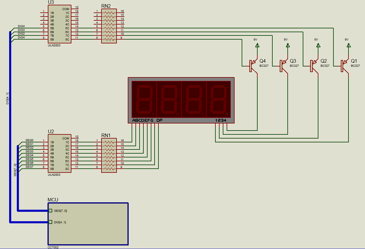
I designed 2 inch display circuit for my project.it is working now but i want to know that is this efficient or require some modifications.Here is a circuit.

Thanks,
display design.JPG
 

Probably, nothing will happens, but possible your mcu will be damaged by appling 9V to pins. There is no reason to use so high voltage. And I see no capacitors for power rails.
Attach whole project that we can edit it.
 

Looks completely wrong to me. The MCU will be damaged and there is no current source for the LEDs anyway, in fact the reversed voltage on the LEDs may damage them too.

Brian.
 

Hi,

i don´t see that it is completely wrong.

only two digits are controlled now.
For sure there are some detailes missing. like microcontroller power supply, capacitors.


If the port voltage is too high for the microcontroller depends on the display forward voltage specification.
Please post complete display specification and updated schematic. With power supply, capacitors, resistor values.....

Klaus
 

sorry for replying late( becouse of network problom).
Here how to avoid damaging of port?can i give segment data through transistor? I did not found datasheet of my 2 inch display by it's part no.I think we can take judgement by similar display specifications.Here i have given circuit with power supply details.
circuit.JPG
 

I don't see any changes that will make this circuit works. If you realy wanna get some help, post complete project so we will be able to edit it.
 

Dear sir,
I designed circuit exactly as given above.actually it is a token no. Display.do you require code?
 

I would expect 10 to 20 mA average and 40 to 80 mA peak segment current for a 2" display. It has multiple LED chips (e.g. 2-4) in series connection, in so far a higher supply voltage than 5 V is required. Due to the forward voltage, the segments can be possibly still driven by a 5V open drain circuit.

The problem is however that 8051 GPIO output currents are far too low to drive the segments at full brightness. You didn't mention any resistor values, I assume that you are respecting 8051 maximum ratings, e.g. 15 mA for bank 3 which limits the segment peak current to about 2 mA.

The current strength of the digit drivers is sufficient for GPIO driven segments, but not if the display shall be operated at full brightness.
 

Better use a display driver IC in order to alter the brightness. It may help you out regarding the power supply issues.
 
  • Like
Reactions: tapu

    tapu

    Points: 2
    Helpful Answer Positive Rating

This is a correct way to connect your display. Voltage allowed till 50V, possible current 500mA per segment.
And take a look how to use buses. They should be named correctly and connected pins will be numbered automaticaly.
 
  • Like
Reactions: tapu

    tapu

    Points: 2
    Helpful Answer Positive Rating
Thank you for helpfull reply.I have modified my circuit.
 

Status
Not open for further replies.

Similar threads

Part and Inventory Search

Welcome to EDABoard.com

Sponsor

Back
Top