Continue to Site

Welcome to EDAboard.com

Welcome to our site! EDAboard.com is an international Electronics Discussion Forum focused on EDA software, circuits, schematics, books, theory, papers, asic, pld, 8051, DSP, Network, RF, Analog Design, PCB, Service Manuals... and a whole lot more! To participate you need to register. Registration is free. Click here to register now.

70MHz peak detector/amplitude detector

Status
Not open for further replies.

itayd100

Junior Member level 3
Joined
Jan 7, 2016
Messages
29
Helped
0
Reputation
0
Reaction score
0
Trophy points
1
Activity points
233
Hello,

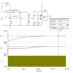
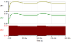
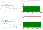
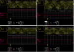
I have a sine wave between 60-70MHz and I want to measure the amplitude of the signal. I thought that the best way is to build a peak detector, but after 10MHz the circuit has hard time to detect the peak.

Any suggestions?

Thanks,
Itay
 

Hi,

* ADC, a lot of samples, RMS calculation.

* lock in amplifier, LPF,

Klaus
 

Hey @KlausST,

Thanks for your answer.

I prefer not to use ADC.
How LPF can help me?
 

Hi,

First you need a fast lock in amplifier, after that you connect a LPF, and the output of the LPF (DC) is proportional to the amplitude.

Klaus
 

Hey,

I think I wasn't clear.
I want to build a circuit that doing that....

Lock in amplifier, is quite complicated to build, not?
 

I have a sine wave between 60-70MHz and I want to measure the amplitude of the signal

Is there some signal carried over this wave and/or at wich rate this wave shifts between 60-70 MHz ?
 

Hey Andre,
I have a sine wave with a fix frequency, let's say 70mhz. The amplitude of the signal is changing and I want to know what is it every moment.
 

Ok, but knowing how the whole signal behaves over the time, as well the specifications expected for the detection, help us to determine the most appropriate solution for your appication in particular, once you had mentioned that must detect peak in a range not too narrow. For example, changes in frequency occur at discontiguous frequency intervals? If not, at what rate occurs this variation (MHz/s)? What is the accepted error?
 

I have used this circuit for a similar purpose on 100 MHz. R2 and R3 can be a 100k trim pot for exact calibration.
 

Attachments

  • peak_det.png
    peak_det.png
    33 KB · Views: 271

There are plenty of opamps with bandwidths in the hundreds of megahertz range. You should be able to couple one of those with a fast diode and cap. You don't say if you want instantaneous peak value or amplitude over many cycles.
 

I'm not sure of your specific requirements, but a simple logarithmic amplifier/RF power detector IC (perhaps preceded by a bandpass filter if there's other signals present you wish to ignore) might fit the bill.

Have a look at Analog Devices' portfolio of chips: https://www.analog.com/en/products/amplifiers/rf-power-detectors.html I've used many of these in the past for all manner of sine wave magnitude measurement from MHz - GHz. One chip, wide dynamic range turnkey solutions!
 

Hey Andre,
I have a sine wave with a fix frequency, let's say 70mhz. The amplitude of the signal is changing and I want to know what is it every moment.
Isn't that pretty much the definition of an AM receiver?
Unless you also want to know the actual carrier frequency (which you say is fixed) then an AM detector can be as simple as a crystal set, and as complex as you like.
Susan
 

Hey @andre,

The frequency will remain the same all the time. The amplitude of the sine wave can be lower, for example: starting with 2Vpp (1 amplitude) and after 5 second suddenly it will go down to 1.5Vpp. I want to be able to measure the "average" amplitude of the 1 second of signal.

I can have error of few precents.

Hey @e-design,

Does the signal change if the amplitude is changing?
I want to be able to measure the "average" amplitude of the 1 second of signal.

Hey @Susan,

I meant something like that:
 

Hey @e-design,

Does the signal change if the amplitude is changing?
I want to be able to measure the "average" amplitude of the 1 second of signal.

It will track the amplitude with some time short delay as shown below.
 

Attachments

  • pulse_det1.png
    pulse_det1.png
    8.8 KB · Views: 168

It will track the amplitude with some time short delay as shown below.
Looks basically good, RR-OP or dual supply needed to track lower input voltages (output cut below 1.6 V now).
I want to be able to measure the "average" amplitude of the 1 second of signal.
Filtering the output with higher time constant for averaging shouldn't be a problem, but it's possibly easier to perform it in signal post processing, e.g. by µC.
 

I'm not sure of your specific requirements, but a simple logarithmic amplifier/RF power detector IC (perhaps preceded by a bandpass filter if there's other signals present you wish to ignore) might fit the bill.

Have a look at Analog Devices' portfolio of chips: https://www.analog.com/en/products/amplifiers/rf-power-detectors.html I've used many of these in the past for all manner of sine wave magnitude measurement from MHz - GHz. One chip, wide dynamic range turnkey solutions!
If you need high accuracy and wide dynamic range, then this is the way to go. I've used the ADL5511 and it's excellent. You would need an attenuator for your large input signal. Unfortunately these convenient RF ICs are only available in surface mount packages.
 

Hey @E-design,

First, thank you very much for your answer.
I built the circuit with the components that I had (like the pic) and I'm getting this reading on the scope (you can look at the pictures).

I get 5V+ half of the amplitude, can I get rid of the 5V? What will be the best way?
I would like to make it smoother, how can I do that?
What simulation program are you using?

Thanks,
Itay


- - - Updated - - -

And this is the schematic:


Try and spot the difference. Sim is with TINA.
 

Attachments

  • det.png
    det.png
    33.3 KB · Views: 173

Hey E-design,

I looked again and my schematic was wrong, I connected it like the top schematic in the picture.
 

I don't understand your issue. Don't construct this on a typical breadboard and expect good results.

Below are results from a circuit I quickly constructed on some copper clad pcb with two 1N5711 diodes. This is with a 50% divider for R2/3. The BAT54A matched diodes should give better results.
 

Attachments

  • det_uncomp.png
    det_uncomp.png
    191.2 KB · Views: 188
Status
Not open for further replies.

Similar threads

Part and Inventory Search

Welcome to EDABoard.com

Sponsor

Back
Top