Continue to Site

Welcome to EDAboard.com

Welcome to our site! EDAboard.com is an international Electronics Discussion Forum focused on EDA software, circuits, schematics, books, theory, papers, asic, pld, 8051, DSP, Network, RF, Analog Design, PCB, Service Manuals... and a whole lot more! To participate you need to register. Registration is free. Click here to register now.

Loop antenna in HFSS

Status
Not open for further replies.

nasibeh_p

Newbie level 4
Joined
Dec 18, 2015
Messages
7
Helped
0
Reputation
0
Reaction score
0
Trophy points
1
Activity points
55
hi everybody,
I have designed a loop antenna in hfss, and I want to see its Magnetic field along its axis.
I have simulate it in Ansoft maxwell and I obtain its inductance 1.8uH.
I have two problems in simulating:
1. what kind of excitation is preferable? I have tried the tutorial of hfss but it didnt give me the right inductance.
2. I can plot E field along axis but not about H field.
what should i do :bang:
 

1. what kind of excitation is preferable? I have tried the tutorial of hfss but it didnt give me the right inductance.

Wave port, but lumped port may also do the trick if needed.

2. I can plot E field along axis but not about H field.

Why not? Are you referring to far-field quantities?
 

Wave port, but lumped port may also do the trick if needed.


Why not? Are you referring to far-field quantities?


no. I really dont know how to plot it. because the relation between E and H field is not constant in near field.
 

HFSS only plots results on previously selected surfaces and only for selected parts of the simulation. If you want to plot the H-field say on the XY-plane, make sure you've selected the XY plane from the Planes tab in the model window. Then right click on your selection, choose "Plot Fields" > "Mag_H". Make sure to select "AllObjects" from the "In Volume" subscreen if you want to plot results for the complete calculated area.
 

Surfaces are not required for field plots. For obvious reasons, you can plot fields inside a volumetric object.

Yes, as long as you select a predetermined surface to do so, like I explained for the globally defined planes in my post.
 

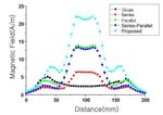
Thanks. but i need a rectangular plot!
I want something like this!

Capture.JPG
 

Thanks. but i need a rectangular plot!

So you want to plot fields along a line.

In this case, your line needs to be drawn before you simulate the structure. Draw the line, run the simulation, then create a new rectangular plot. Under "Geometry" in the top left corner, select your line. Then you can plot various field quantities.
 

So you want to plot fields along a line.

In this case, your line needs to be drawn before you simulate the structure. Draw the line, run the simulation, then create a new rectangular plot. Under "Geometry" in the top left corner, select your line. Then you can plot various field quantities.
Thanks alot. Ive already done this but there is no H field to plot, I have only e-field!
 

Loop antenna equivalent circuit

I have simulate a loop antenna in HFSS, in order to see L, R_ant, C_ant and its H field. I can see its L but I dont have any idea about calculating C_ant.
I have one more problem about its resonance frequency, I want it to resonate at 13.56, but its resonance freq is about 110 MHz.
 

Re: Loop antenna equivalent circuit

A 13.56 MHz "antenna" (or inductive coupler) has no significant self capacitance. It can only resonate with an external capacitor.
 

Re: Loop antenna equivalent circuit

A 13.56 MHz "antenna" (or inductive coupler) has no significant self capacitance. It can only resonate with an external capacitor.

thanks alot. But in nxp documents a Ca is considered for antenna equivalent circuit at its resonance frequency. How can I calculate L, C and R of antenna in its resonance frequency?
 

Re: Loop antenna equivalent circuit

Oops! I made mistake!! Its very easy to calculate C!!!
but I have another problem!
at the low frequency end, the inductance begins to increase. According to the theory, when frequency is approaching to zero, the inductance should approach its DC value. Not sure why here it starts to increase.
 

Hi nasibeh, can you share your file loop antenna file with me, please?
 

Re: Loop antenna equivalent circuit

Hi nasibeh, I also get the same result no matter in simulation or measurement, which at low frequency (such as 1 MHz) inductance will decrease from higher value to DC value with frequency increasing. In my design the inductance is 180 nH, but the inductance at 1 MHz is around 190 nH and at 10 MHz the inductance is around 180 nH.

Did you figure it out?
 

Status
Not open for further replies.

Part and Inventory Search

Welcome to EDABoard.com

Sponsor

Back
Top