MTrolle
Junior Member level 2
Hi everyone,
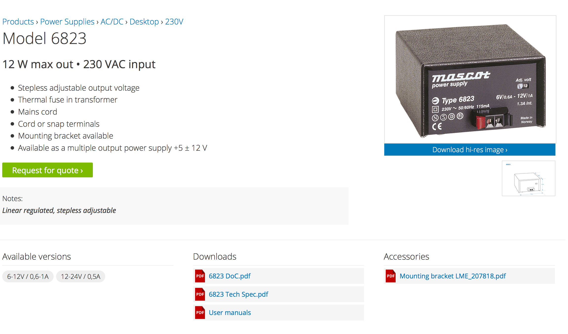
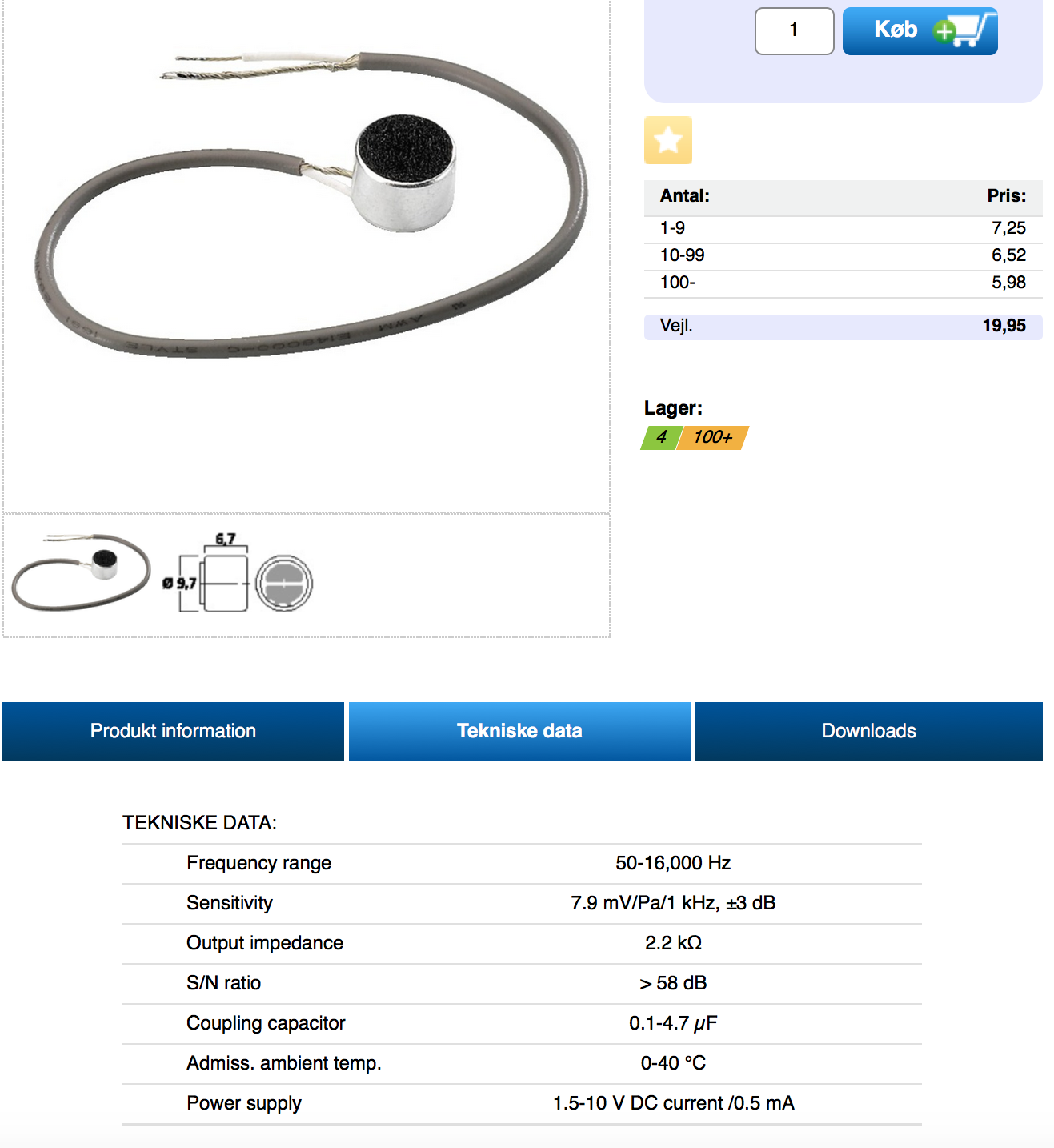
I am a super novice at this stuff, but I have made a "sound system". A speaker unit with 3 channels, which can listen to the 3 channels simoutanously or by demand. On the microphone unit you can setup the channels.
I want to reduce the "background" noise / noise from the amplifier. There are way too much noise, when all 3 channels are active at same time. How can I possible do this the easiest or the best way?
I hope you understand the problem and you're able to help somehow. I am very thankful for any suggestions.
Best Regards,
Michael Trolle
")