Continue to Site

Welcome to EDAboard.com

Welcome to our site! EDAboard.com is an international Electronics Discussion Forum focused on EDA software, circuits, schematics, books, theory, papers, asic, pld, 8051, DSP, Network, RF, Analog Design, PCB, Service Manuals... and a whole lot more! To participate you need to register. Registration is free. Click here to register now.

s21 and s12 parameter in lna

Status
Not open for further replies.

Avinash Akotkar

Junior Member level 3
Joined
Sep 27, 2015
Messages
28
Helped
0
Reputation
0
Reaction score
0
Trophy points
6
Activity points
261
here all
here i am designing current reuse lna in cadence and i got s11 = -24 db and s22 = 26db but s12 = s21 = -44 db
what parameter should i change to get proper output at 2.4 Ghz at 0.18um technology
 

Welcome Avinash Akotkar,

I'd start with whatever fixes your scattering parameters. S22 should not be larger than 0dB, and one of S12 or S21 should be larger than 0 dB if amplification is occurring.
 

input and output return loss (S11 and S22) tells you how much energy reflected back from the load. so it has to be as low as possible and surely < 0dB as planar metamaterials said. typical value wil be < -12dB.

S21 is you LNA gain. it has to be higher and typically can vary from 8dB to higher depending upon device used.

S12 is isolation/reverse gain. you want it to be as low as possible.

something really wrong with your simulation. i cant suggest anything yet since the results doesnt make sense!
 

thanx but i have done changes at output impedence and got s22 = -28db but s12 and s21 remains same

- - - Updated - - -

I have done changes at output impedence and got s22 = - 28db which is better but s21 and s12 remains same
please provide me suggestion
 

now S11 and S22 is fine. S12 and S21 still doesnt make sense. since your S11 and S22 is good, your S12 and S21 suppose to be good! check your simulation setup and make sure you are doing the right thing.
 

Your LNA is not Stable, it would oscillate..
 

Actually in schematic resisitor not connected properly and after proper connection i found following result
s11=-25.86db
s12=-62.90db
s21=-19.97db
s22=-28.021db
NF = -2.9176db
is this result are ok

actually NF is 2.9176 db
 
Last edited by a moderator:

To stop guessing, please post a picture of your simulation setup. A negative noise figure would be great and should make a patent of your circuit :). Seriously, post a pic. Because you have no amplifier but an attenuator.
 

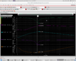
s-parameter result.png
plese attched file
give me reply about work
 

So you have an amplification and a positive noise figure. The results are ok but I meant to post a pic of your schematic.
 

Status
Not open for further replies.

Similar threads

Part and Inventory Search

Welcome to EDABoard.com

Sponsor

Back
Top