nmit.201
Newbie level 2
Hi All,
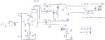
I am trying to design a multi output SMPS deriving the following rails.
1. +3.3V - 1A, Continuous Operating Current - 300mA. Minimum Idle Current - 150mA. Regulation less than 5%.
2. +5V - 2A, Idle Current - 200mA, Continuous Operating Current - 1A. Regulation less than 5%.
3. +12V - 0.5A, Idle Current - 50mA, Continuous Operating Current - 300mA, Regulation about 10%
4. -5V - 0.5A - Idle Current - 25mA, Continuous Operating Current - 200mA
I have attached the schematic for this design along with board design. The SMPS will power electronics required for my custom application. All are resistive loads and do not have any inductive loads. Board design is done in accordance with recommended board layout by PIExpert.
1. Can somebody review the schematic and board designs? This is my first SMPS design and hence have played safe w.r.t cross regulation by including LDO's at the output.
2. I have added some LED's at the output to indicate power in rail, and can this act as the bleeder to discharge the capacitor charge once SMPS is turned off or should I add a separate circuit for this?
Regards,
Manju