Williev
Newbie level 1
Guys,*
Its been awhile since ive delt with electronics. It's really been about 20 years. I'm getting back into it and need some help.*
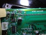
What i'm doing here is just replacing some SMT capacitor's. Seems simple enough right. Well this circuit was made back in the 1980's. When taking off some of the capacitors, I really didnt have todo anything. They were just falling off with the slightest touch. Along with the capacitors, came the metal that connects it to the circuit board. So now there are a couple spots where no soldier will stick. There are a couple place where I cant trace where it would connect in the circuit because the board was messed up. I have included photos.*
Looking at the photo. I need to put a capacitor in C102 ... But where is the negative going?
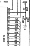
A crop from the schematic is also included below.
So Looking at the crop of the schematic, I want to make sure im reading this right. So coming off the chip 380-1B at pin 20. That is the positive. the path then splits and part goes to FB5 and the other goes to the capacitor C102 (16V 10uF). The negative of the capacitor just goes to a chasis ground. So I can really tact that to any ground.*
Correct?
Once again sorry for all the newbie questions.*


Last edited by a moderator: