Continue to Site

Welcome to EDAboard.com

Welcome to our site! EDAboard.com is an international Electronics Discussion Forum focused on EDA software, circuits, schematics, books, theory, papers, asic, pld, 8051, DSP, Network, RF, Analog Design, PCB, Service Manuals... and a whole lot more! To participate you need to register. Registration is free. Click here to register now.

Questions about RCC switch mode power supply – Circuit by Andy

Status
Not open for further replies.

samy555

Full Member level 4
Joined
May 11, 2010
Messages
207
Helped
0
Reputation
0
Reaction score
0
Trophy points
1,296
Location
Palestine
Activity points
2,963
Hello
From: **broken link removed**
I read all the page and have some questions and hope someone (like Jony130) respond
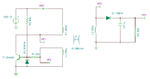
Q1) Can someone give values for the circuit below as it is,,, I know it is a basic circuit but I want to build it and see some waveforms on my new oscilloscope.

**broken link removed**​
Q2) If Rs = 100Kohm and VCC = 12Vdc then IB = about 113uA
This current will maintain the Q1 always ON. How Q1 be OFF in other period of time?
Tomorrow I will put more questions
Thank you
 

This appears to be a blocking oscillator. The principle of operation is not readily obvious.

Current increases through the transformer, until it reaches saturation. As flux stops changing, induced current drops suddenly. This turns off the transistor. The process repeats.

With the right half of the circuit, it acts as a flyback converter.

A similar principle makes the 'joule thief' work.

Values for RS & RB must be adjusted by experimentation.
 
  • Like
Reactions: samy555

    samy555

    Points: 2
    Helpful Answer Positive Rating
The values are not that critical. The circuit below should put you in a good starting point to study the wave-forms.
If you don't want to wind your own transformer, you can use an off-the-shelf pulse transformer. This model was used in the simulation.
 

Attachments

  • PSU1.png
    PSU1.png
    38.6 KB · Views: 84
  • PSU.png
    PSU.png
    11.8 KB · Views: 81
  • PSU2.png
    PSU2.png
    24.1 KB · Views: 80

Start out with RS=10kΩ and RB=1kΩ and go from there.
Observe the voltage at the transistor collector.
If the circuit does not oscillate change the value of RS either up or down.
If the transistor is not saturating when ON (Vc less than a volt) then reduce the value of RB.
To determine the minimum value of RB needed, you can keep increasing its value until the transistor comes out of saturation when ON. You then want a value about 1/2 of that.

What transformer are you using?

Note to provide some output load (say 100Ω) or the voltages can become very high and zap something.
 

This appears to be a blocking oscillator. The principle of operation is not readily obvious./QUOTE]
I read the above phrase and went immediately to Google and got many website, the most important –for me- among them was:
http://www.interfacebus.com/transistor-blocking-oscillator-circuit.html
From which I was able to get a good perception on the subject
This in itself was a big help because I knew about what I asked. Thank you BradtheRad
Current increases through the transformer, until it reaches saturation. As flux stops changing, induced current drops suddenly. This turns off the transistor. The process repeats.
With the right half of the circuit, it acts as a flyback converter.
A similar principle makes the 'joule thief' work.
Values for RS & RB must be adjusted by experimentation.
Note that both the joule thief and the blocking oscillator circuits have the collector and base coils wound oppositly (180 degree out of phase). This is not the case of our first circuit. Is this a big difference in the performance of both circuits?
 

..................
Note that both the joule thief and the blocking oscillator circuits have the collector and base coils wound oppositly (180 degree out of phase). This is not the case of our first circuit. Is this a big difference in the performance of both circuits?
I see no difference. The first circuit (in your initial post) has the collector and base transformer connections opposite polarity.
I think you just looked at it wrong.
 

Status
Not open for further replies.

Similar threads

Part and Inventory Search

Welcome to EDABoard.com

Sponsor

Back
Top