Continue to Site

Welcome to EDAboard.com

Welcome to our site! EDAboard.com is an international Electronics Discussion Forum focused on EDA software, circuits, schematics, books, theory, papers, asic, pld, 8051, DSP, Network, RF, Analog Design, PCB, Service Manuals... and a whole lot more! To participate you need to register. Registration is free. Click here to register now.

[SOLVED] High Frequency Peak Current in Batteries

Status
Not open for further replies.

Mikezz

Newbie
Joined
Dec 9, 2015
Messages
3
Helped
0
Reputation
0
Reaction score
0
Trophy points
1
Activity points
39
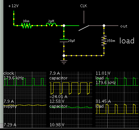
Hey guys, I am currently building a battery powered flyback transformer that uses an ne555 timing chip at 180KHz. The peak current i have worked out will be 29.6A on the primary side of the flyback with the average current being 7.4A.

My question is if I use a battery meant for quad copters with 2200mAh and a discharge rate of 8c (max current of 17.6A) can it handle the peak currents of 29.6A at 180KHz? I have read that at high frequencies above 1KHz that batteries act differently and can draw more current than their maximum discharge rate shown without damage but im just not sure about 29.6A compared to the maximum of 17.6A. Or does all this not matter and i just need to go off of the average current for this circuit and not worry about peak current?

If anyone could tell me if this battery would work or not that would be really helpful, thanks.
 

https://www.mpoweruk.com/life.htm

"For pulsed applications the peak load on the battery can be reduced by placing a large value capacitor in parallel with the battery. Energy for large instantaneous loads is supplied by the capacitor effectively reducing the duty cycle and stress on the battery. The capacitor recharges during the quiescent periods. Claims of a sixty percent increase in cycle life are made for this technique.

Another benefit of this arrangement is that since the battery supplies less of the instantaneous peak load current, the voltage drop across the battery will be lower. For high power pulses this voltage drop can be very significant."
 
  • Like
Reactions: Mikezz

    Mikezz

    Points: 2
    Helpful Answer Positive Rating
If you regard the internal construction of a battery as series of inductances with shunt capacitors, at high frequencies, all the action goes on in the plates area, nearest the terminals. At steady DC conditions, the whole area of the plates are used and the battery life is extended. Well not really, this is just the quoted life. High frequency ripple on the charging current causes micro charging and shortens battery life. As told to me by a battery rep.
Frank
 
A common mistake is to assume that a battery is just a large capacitor. It is not.

For a variety of reasons, electrochemical reactions tend to crowd at certain location, creating "hot spots". These spots become worn prematurely.

Since I remember, every large power battery application I've seen has had a parallel capacitor.
 
Also consider adding an inductive choke in the power line (in addition to the capacitor as recommended in post #2). The effect is to smooth current drawn from the battery.

This method is practical for large Ampere draw, and fast switching frequency. This allows the choke to be a small Henry value.


The simulation is greatly simplified. Notice the output stage has pulses of 30A. Yet the power supply is smooth 7A.
 
Thank you so so much, really helped.
 

Status
Not open for further replies.

Similar threads

Part and Inventory Search

Welcome to EDABoard.com

Sponsor

Back
Top