Continue to Site

Welcome to EDAboard.com

Welcome to our site! EDAboard.com is an international Electronics Discussion Forum focused on EDA software, circuits, schematics, books, theory, papers, asic, pld, 8051, DSP, Network, RF, Analog Design, PCB, Service Manuals... and a whole lot more! To participate you need to register. Registration is free. Click here to register now.

big 7 segment common cathode display advice

Status
Not open for further replies.

pasicr

Advanced Member level 1
Joined
Aug 13, 2005
Messages
440
Helped
39
Reputation
80
Reaction score
29
Trophy points
1,308
Location
Macedonia
Activity points
4,213
Hi there,
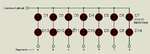
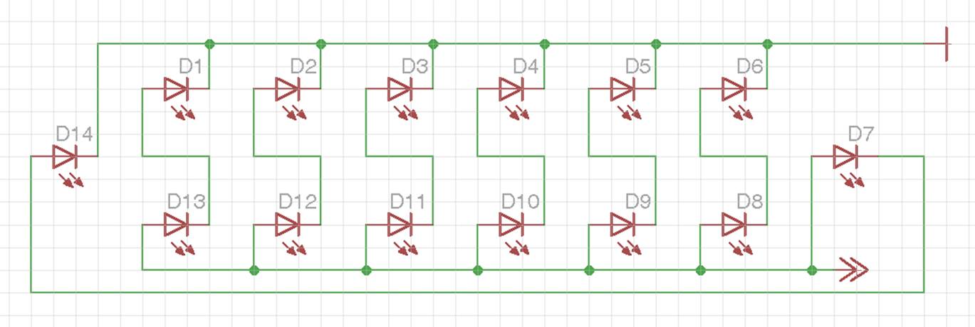
I have 7 segment common cathode display,
each segment look like on attached image,
5mm red color led's


I will use 12VDC to drive it, total 2 seven segment common cathode display, for countdown show...
I need advice how to calculate limited resistor value,

or how to connect common cathode and each anode to PIC MCU to avoid burning port, and to reach max led's brightness,

thanks
best regards
 

driving the LEDs directly from MCU is not advisable.
have a driver , transistor or IC based for display.

in your diagram , you have shown two diodes in each segment.

check whether it is two diodes in series or in parallel.
based on which , the resistor can be calculated.
 
  • Like
Reactions: pasicr

    pasicr

    Points: 2
    Helpful Answer Positive Rating
Thanks Srizbf for your replay,
according the image I have 7 pairs (each with 2 diodes in series) of parallel diodes on each segment,
can I use ULN driver, 2003 or 2803?
connection diagram?
 

that is , there are two led diodes in series in each segment. right?

first make sure that your display is common cathode type.
your diagram does not give the same.
 
  • Like
Reactions: pasicr

    pasicr

    Points: 2
    Helpful Answer Positive Rating
Hello pasicr

The electrical characteristics of the LEDs in the ISIS Proteus simulator are:
2.2 Volts when they are crossed by 10mAmp.
2.2 Volts is the parameter called VF. (Forward Voltage).
10mAmp. is the parameter called IF. (Forward Current).

The formula to find the value of current limiting resistor for the segments of the display that you mention would be: (Vcc - (Vf1 + Vf2)) / If = Rx.

You say in your original message that you are polarizing, these Display's, with 12VDC. But you need to know the IF parameter and the VF parameter to find the value of Rx.

Let's assume that your Display LED’s have the same characteristics as the ISIS Proteus simulator, then:
(12 - (2.2 + 2.2)) / 0.010 = 760 Ohms = Rx.

Now, your second question:
how to connect each common cathode and anode to PIC MCU to avoid burning port, and to reach max brightness LEDs,

First, you have to analyze the data sheets of the PIC you're using to find out if the PIC can handle the stream of your Displays.
Second, how will you handle displays in a multiplexed system or how. ??

I think that your display would be more understandable drawn as seen in the attached image.
 

Attachments

  • Big 7 Segment Dislay CC.png
    Big 7 Segment Dislay CC.png
    91.2 KB · Views: 127
  • Like
Reactions: pasicr

    pasicr

    Points: 2
    Helpful Answer Positive Rating
Thanks Carlos for detail explanation,
to avoid misunderstood I need to explain that my attached image show only one segment from my 7 segment display,
I have 7 x

on each display,
that is definitely common cathode 7 segment display, because on PCB I see one common GND pin and separated pins for SEG A to G and DOT segment

here is image from my 7 seg display
IMG_20151207_082439.jpg
 
Last edited:

your photo cleared the ambiguity in the post.

each segment of display is made up of the arrangement shown in your earlier diagram.

ULN2003 or uln2803 cannot be used straight away.
 
  • Like
Reactions: pasicr

    pasicr

    Points: 2
    Helpful Answer Positive Rating
Hello pasicr

So, each segment has 14 LEDs connected in Series-Parallel and the DP has 4 LEDs connected the same way as the segments.

Have You the part number for this display?.
Or it is homemade?
Either way we need to know the electrical characteristics of LEDs containing In this Display In order to advance.

By the way, currently in Mexico is 02:02 a m.
I'm going to sleep. Bye
 

Hi,

you need to know the parameter of a single LED.

* maximum DC current (I_F)
* forward voltage at max. DC current (V_F)

Because there are two LEDs in series (7 times)
--> there is a total segment forward voltage of twice the LED V_F

Because there are seven circuits in parallel
--> the total segment forward current is 7 x I_F

VCC is the drive voltage.
--> then R_L = (VCC - 2 x V_F) / (7 x I_F)

Paralleling LEDs is not recommended --> expect difference in brightness.
Most probably the segment forward voltage is about 4...4.5V, so using 12V is a wayste of power = much heating in your R_L
Power dissipation in R_L = (VCC - 2 x V_F) x (7 x I_F)

Klaus
 

Hello pasicr

First of all, as srizbf says in his message #7: You can not use the IC's ULNxxxx.
Unless you make your Display's as common Anode.

You can probably use 2 BJT PNP transistors connected in Darlington configuration.
One pair for each segment of the display with their respective current limiting resistors for each pair of LED’s
But we need to know the current required by each segment to select a suitable transistor.

Carefully studies the circuit I'm attaching you; In PDF format or developed with ISIS Proteus simulator contained in the .ZIP.

The data sheets of the IC's ULNxxxx can find this link: https://www.alldatasheet.com/ and download them to your PC so you can see why it is not possible to use for your design.

If You do not find the electrical characteristics of LED’s that you are using, we will have to do an experiment to know them.
 

Attachments

  • Big 7 Segment Dislay CC.PDF
    621.4 KB · Views: 133
  • Big 7 Segment Dislay CC.zip
    20.8 KB · Views: 107
Last edited:
  • Like
Reactions: pasicr

    pasicr

    Points: 2
    Helpful Answer Positive Rating
Status
Not open for further replies.

Similar threads

Part and Inventory Search

Welcome to EDABoard.com

Sponsor

Back
Top