prcken
Advanced Member level 1
Hi
I am currently using HFSS simulating a grounded CPW T-line on silicon substrate.
I tried with both Wave port and lumped port. But I got very different results.
I read that a lot saying that it needs to meet the minimum sizing for wave port depending on the width and spacing of the CPW parameters. I am sure my wave port size is big enough. Is there a problem that the wave port is too big?
I am so confused.
Any comments or suggestions?
Thanks!
Wave port setup: the wave port touches 1 signal terminal and 2 ground terminals, for ground, set terminal renormalization to 0.001 Ohm

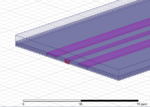
Lumped port setup: i used PEC sheets connect two ground traces to the ground plane PEC. Air box didn't display in the picture below.

S-parameters got form wave port, de-embedding function used.

Worse S-parameters got form lumped port for the same length

wave port field display on signal terminal (zoomed-in)

I am currently using HFSS simulating a grounded CPW T-line on silicon substrate.
I tried with both Wave port and lumped port. But I got very different results.
I read that a lot saying that it needs to meet the minimum sizing for wave port depending on the width and spacing of the CPW parameters. I am sure my wave port size is big enough. Is there a problem that the wave port is too big?
I am so confused.
Any comments or suggestions?
Thanks!
Wave port setup: the wave port touches 1 signal terminal and 2 ground terminals, for ground, set terminal renormalization to 0.001 Ohm

Lumped port setup: i used PEC sheets connect two ground traces to the ground plane PEC. Air box didn't display in the picture below.

S-parameters got form wave port, de-embedding function used.

Worse S-parameters got form lumped port for the same length

wave port field display on signal terminal (zoomed-in)

Last edited: