wizpic
Advanced Member level 3
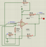
I have a circuit set up as differential input with op-amps running of a -/+5V supply, this is so it can measure current flow in either direction it boosts the voltage from 0-60mV to 0-3.73V and the other part converts the signal to a positive voltage regardless current flowing in and out.
This is working very good but I would like to a - sign when current is flowing out the opposite direction on the LCD to so user that it's having current drawn rather than charging.
So the question is how can I add something that will convert the -0 to 3.73V in to give logic high(5v) and remain logic low (0V) when voltage is + 0 to 3.73 volts. I've attached the first part of the circuit to show how it works
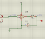
I've looked at the compactor op-amp (only in sim), With a current draw of 5amps and -0.757v on the input of the lm393 the output swings high to 5V, I would like to go lower say 1amp with -0.412V (or even half an amp)I would like it to swing high to 5V, Tried changing the resistor values but still it only swings at -0.757V. See pic below
Is there away to achieve this
This is working very good but I would like to a - sign when current is flowing out the opposite direction on the LCD to so user that it's having current drawn rather than charging.
So the question is how can I add something that will convert the -0 to 3.73V in to give logic high(5v) and remain logic low (0V) when voltage is + 0 to 3.73 volts. I've attached the first part of the circuit to show how it works
I've looked at the compactor op-amp (only in sim), With a current draw of 5amps and -0.757v on the input of the lm393 the output swings high to 5V, I would like to go lower say 1amp with -0.412V (or even half an amp)I would like it to swing high to 5V, Tried changing the resistor values but still it only swings at -0.757V. See pic below
Is there away to achieve this