Continue to Site

Welcome to EDAboard.com

Welcome to our site! EDAboard.com is an international Electronics Discussion Forum focused on EDA software, circuits, schematics, books, theory, papers, asic, pld, 8051, DSP, Network, RF, Analog Design, PCB, Service Manuals... and a whole lot more! To participate you need to register. Registration is free. Click here to register now.

push pull driver does not work

Status
Not open for further replies.

wormux29

Newbie level 4
Joined
Nov 20, 2015
Messages
5
Helped
0
Reputation
0
Reaction score
0
Trophy points
1
Activity points
36
Hi All.

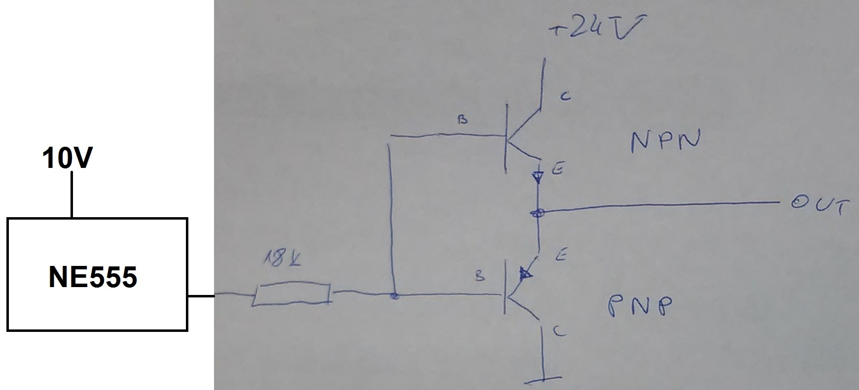
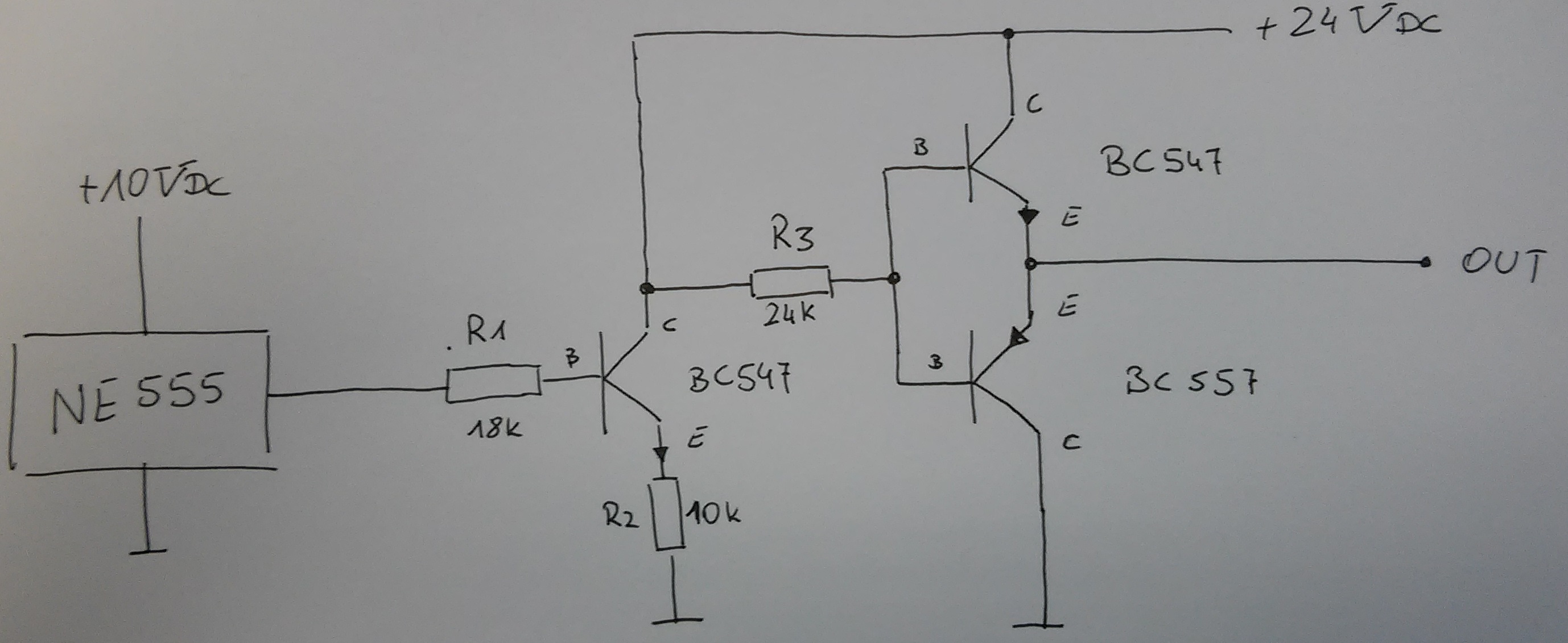
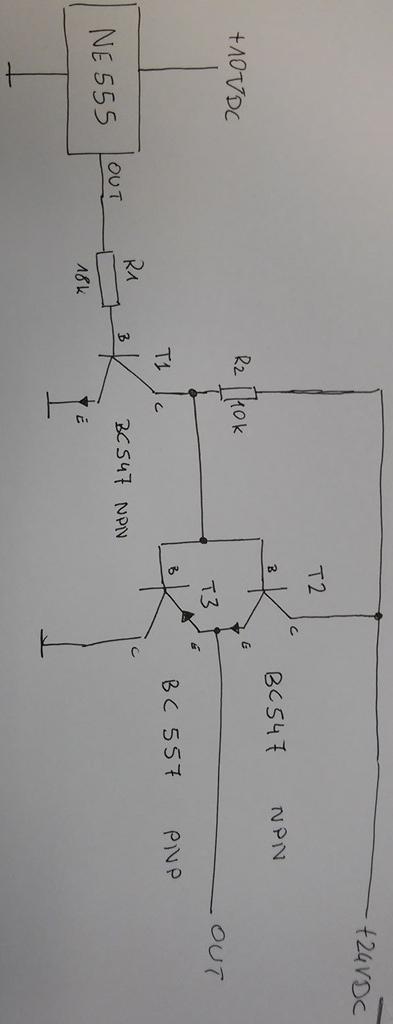
I made circuit as shown in picture. Output signal is connected trough resistor to base of transistors. The waveform at the output is correct but signal amplitude is 9V. I expected amplitude equal 24V. Could you please help me a litle bit. Why it dose not work :)

I will be grateful for any help you can provide.

Best regards.


Hi,

The output voltage can not be larger than the input signal voltage at the base.
It is a current amplifier only, but no voltage amplifier.

Klaus
 
You need a driver with level translation, more than two transistors are required to make it. Why don't you use an off-the-shelf integrated driver like TC427?
 

Hi.

Klaus you thinking about something like in picture below?


Hi,

With mosfets it is the same. In this circuit they amplify current only.

A simple solution could be an extra npn and a base current limiting resistor.

-->
Disconnect line between port and your_bases.
New npn, emitter to gnd, base with series resistor to port.
Collector to your_bases, pullup to 24V.


Klaus

- - - Updated - - -

Hi,

Almost correct...

Collector to your_bases, pullup to 24V.

Means: drect connection between collector and your_bases, witout resistor.
AND pullup resistor form collector to 24V.
AND no resistor in emitter path

Klaus
 

Hi.

Many many Thanks :) so the final version can looks like this? Is it right now :)


Hi,

looks good.

Maybe you face some problems:

If you need more source current then decrease R2.
If the output_voltage_low of the NE555 is too high, then add a 10k at B and E of T1 (to safely switch T1 OFF).

Klaus
 
One more time thank you, it was very helpful. I'll try this circuit. Is it good practise to always use additional resistor between B and E.
 

Status
Not open for further replies.

Similar threads

Part and Inventory Search

Welcome to EDABoard.com

Sponsor

Back
Top