Continue to Site

Welcome to EDAboard.com

Welcome to our site! EDAboard.com is an international Electronics Discussion Forum focused on EDA software, circuits, schematics, books, theory, papers, asic, pld, 8051, DSP, Network, RF, Analog Design, PCB, Service Manuals... and a whole lot more! To participate you need to register. Registration is free. Click here to register now.

required resistor values to increase power transistor in parallel in this circuit

Status
Not open for further replies.

SAMYA

Newbie level 4
Joined
Jan 19, 2014
Messages
7
Helped
0
Reputation
0
Reaction score
0
Trophy points
1
Location
INDIA
Activity points
52
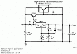
I want to fetch more current from this configuration that's why i want to increase the no of power transistors in parallel.My question is if i add more power transistors in parallel,then what will be the value of R2 & R3 and what is the formula to calculate them.Also what is the proper value of star marked resistor.Right now i'm using 2n3906 instead of 2n3905 and TIP35 as the power transistor and 1.5k as the star marked resistor.This is my first post here,so please regret any mistakes....
 

Attachments

  • LM317.gif
    LM317.gif
    33.3 KB · Views: 82

LM195 isn't a simple power transistor, it's an IC with special properties. Please consider that regular bipolar power transistor won't achieve equal current share in parallel operation without additional means like a feedback emitter resistor.
 

But here in TI's datasheet,this design is using TIP73(Normal BJT).Also my configuration runs correctly......:smile:LM317_1.gif
 

I think the asterisked resistor is used to draw 30mA at no real load, it's so the regulator functions correctly until the real load draws >30mA, so you can calculate this resistor based on the regulator output voltage. Not sure if it's good practice, probably not a great way to do it, three (fairly matched) LEDs could draw the 30mA with an appropriate value current limiting resistor instead.
 

I am designing an adjustable dual voltage regulator using LM317/337.So the output voltage will be varying.So if i have to calculate the resistor to draw 30ma then what voltage should i choose as it will be varying and the current will also vary????
 

But here in TI's datasheet,this design is using TIP73(Normal BJT).Also my configuration runs correctly......
Why "but"? You have been asking about paralleling multiple transistors, this is no parallel circuit.
 

As you said that LM195 is a special chip that's why i mentioned but as the second circuit is using normal BJT....
 

When Texas Instruments copied the circuit from the National Semi datasheet they made a HUGE MISTAKE by changing the VERY sensitive LM195 to an old ordinary VERY low sensitivity power transistor.
The circuit is too simple to make a variable voltage power supply because the power transistor does not have a driver transistor. Instead it has a 500 ohm resistor to provide the low base current needed by an LM195.
 

If this circuit is wrong using a BJT,then how it is working with TIP35 in my setup??Previously i tried the circuit with TIP36/TIP42 without the 2n3905,R2,R3 & the star marked resistor and i fried almost 10 bjts as they all were getting fried whenever i put load on the output.As long as nothing was connected,every thing was fine.But whenever i was connecting a load,the PNP pass was like "BOOM" .....i checked my PNP circuit several times but no errors found in the wiring...then i built this circuit with NPN pass and small PNP and is now woking well....but i need the resistor values to achieve more output current....
 

I am unable to comment on why your simulation works now, and about other pertinent information offered in this thread.
If that asterisked resistor is definitely for minimum load and you are making a variable supply, you would have to "square the circle" and calculate resistor value for lowest voltage and highest output voltage. Surely it isn't that huge a difference? 5V/0.03A = 167 ohms; 30V/0.03A = 1000 ohms... Or maybe it is.
It probably doesn't help much, but trying to interpret voltage regulator schematics (the inner workings) is a way of comparing what you are making to what you want to achieve, and any additional or unsuitable building blocks you may need to achieve this. Some power supply schematics look like one big voltatge regulator circuit.
 

You have not mentioned how much current you want to draw. All power transistors suffer from amp cramp, that is when they have to pass an amp or more their Hfe fall to low values, 20 or even lower. This means that the driver must be rated to pass 50 mA or more for every amp the output transistors are passing. paralleling output transistors means that each power transistor is passing , say .3A so its Hfe is likely to be 50 or so, but the combined base current is still 18 mA, which is pushing your tiny little driver transistor.
Frank
 

The LM195 was basically a NPN common-emitter voltage amplifier with a threshold of 0.6V and an NPN Darlington Emitter Follower. It's performance was like a FET with a threshold of Vth=0.6V witha n RdsON of ~1Ω but with an extra diode drop on the output. The advantage of the LM195 was that it was rugged with current limit protection but not nearly as low RdsON as HEXFETs or modern power MOSFETs.

Also compared to smart high side automotive switches, it had poor cost*Vdrop performance, so when they changed LM195 to obsolete for new design then phased out.

This is not the 1st time an old product had an error in the application schematic, but then since it was just an example without specs, there are no numbers to benchmark.

TO make it behave better would require the Rb to change from 5k to a much lower value dependent on specs so it might be 10 Ω or 100Ω with a Darlington driver but depends on other factors like , how much much heat you can stand in this coffee cup warmer linear regulator.

Then again one could use a MOSFET bypass or even smarter...., add an inductor and make it into a SMPS.
And stilll smarter again.. use a common buck regulator IC.

There are just so many better choices these days.

Next time I insist you add specs with a question, like output current< load regulation, supply power and regulator heat loss.


But to answer your original simple question ;)
.. the simple answer is a constant current sink.

Since the design was a variable voiltage, the resistor must be variable with a need to turn on Vbe with 0.7V, so a 35mA CC sinkis better for load regulation at low In-Out voltage drops. This requires 2 transistors and 2 resistors... sorry no simple answer. :laugh:

Tony S
 
Last edited:

I am redesigning the circuit with MOSFETs.I have IRF150 in stock.Please suggest me Pfet version of this MOSFET.
 

Sorry....typing mistake....MOSFET no is IRFP150.....Please suggest P channel MOSFET for this one
 

Hi,

If the same idea as post #1 schematic, ooohhh..., I was going to do the same thing with a power supply, until a member here pointed out that MOSFETS are not helpful in this way: more current is more voltage "lost", it's that parameter Vgs I think you need to bear in mind...
 

Status
Not open for further replies.

Part and Inventory Search

Welcome to EDABoard.com

Sponsor

Back
Top