Spork
Member level 3
Hello EDAboard, it has been a while.
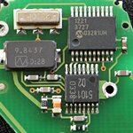
I have a circuit that I would like to learn more about and I am hoping some of the more EE educated folks can give me a hand. I am attaching a photo of the circuit and a few details of what I know.
This is an RF transmitter circuit that operates at 315Mhz, It uses a standard CR2032 3v battery as a power source, and As best I can the board was made in 1997.
So far the components I see on the circuit look like this:
-----
At this point I assume the Microchip component is a microcontroller with the information to be transmitted and the MAXIM chip is used as a Direct RF transmitter.
To further my knowledge, I have 3 tasks and I am open to suggestions for more:
1) Draw out the circuit diagram in hopes of getting a better understanding of components. If I have to desolder this may come last, or I will desolder and break it out on a breadboard to do further analysis. -- This should help me understand if the Direct RF theory is right.
2) 'Listen' to the RF data using a USB SDR.
3) Hook up a logic analyzer to the data on the Microchip component to see if I can glean more information that way.
I have a circuit that I would like to learn more about and I am hoping some of the more EE educated folks can give me a hand. I am attaching a photo of the circuit and a few details of what I know.
This is an RF transmitter circuit that operates at 315Mhz, It uses a standard CR2032 3v battery as a power source, and As best I can the board was made in 1997.
So far the components I see on the circuit look like this:
Code:
IC1:
Mfg: Microchip
Function: Presumably this is a microcontroller, but I don't come up with anything by searching the markings on the chip.
Markings:
1221
3727
(M) 03281UH
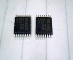
IC2:
MAXIM
MAX5101
Markings:
0
3 5101
3 D2
8
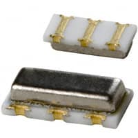
XTAL1:
Mfg: ? (Don't know, don't think it matters)
Function: 2Mhz Crystal Oscilator?
Markings:
2000 MF
XTAL2:
Mfg: NDK
Model: NX8045GB
Function: 9.8437Mhz Crystal
Markings:
9.8437
[N] D:28-----
At this point I assume the Microchip component is a microcontroller with the information to be transmitted and the MAXIM chip is used as a Direct RF transmitter.
To further my knowledge, I have 3 tasks and I am open to suggestions for more:
1) Draw out the circuit diagram in hopes of getting a better understanding of components. If I have to desolder this may come last, or I will desolder and break it out on a breadboard to do further analysis. -- This should help me understand if the Direct RF theory is right.
2) 'Listen' to the RF data using a USB SDR.
3) Hook up a logic analyzer to the data on the Microchip component to see if I can glean more information that way.