Continue to Site

Welcome to EDAboard.com

Welcome to our site! EDAboard.com is an international Electronics Discussion Forum focused on EDA software, circuits, schematics, books, theory, papers, asic, pld, 8051, DSP, Network, RF, Analog Design, PCB, Service Manuals... and a whole lot more! To participate you need to register. Registration is free. Click here to register now.

PFET load switching issues

Status
Not open for further replies.

jstamour802

Junior Member level 1
Joined
Jul 22, 2009
Messages
19
Helped
1
Reputation
2
Reaction score
1
Trophy points
1,283
Location
USA
Activity points
1,591
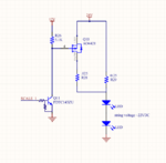
I have a circuit that needs to "scale" the output current, but doing so with this circuit does not always work. The PFET will not turn OFF regardless. If I reduce the 24V rail down to a smaller value than VG (12V), it will shut off.

I realize I probably screwed up this circuit, since the relationship of VGS will always keep this FET ON..


Can someone guide me to a solution.. is there anything I could do here to make this work?


Thanks
pfet_load_switch.png
 

I believe You need a Diode between the Collector/Resistor Connection and Gate, to Offset the Collector to Emitter Voltage.
You will also need to Add a Gate to Source Resistor.
 

If the transistor is ever turns on then it would apply almost 0V to the gate which would probably destroy the Mosfet because its maximum allowed gate-source voltage is 20V.
What is the purpose of the circuit? If it works then the LEDs would always be turned on and would be only slightly brighter when the Mosfet turns on.
 

Can you recommend a circuit that might work here? If I lower the string voltage (the 24v rail), the circuit works

The purpose of this circuit is to "scale" the output. This schematic is simplified; these resistors are sensed by an LED driver to regulate output current.

The goal is to change the total sense resistance, so that the driver can maintain current regulation when the output load requires a very low setting, so I need to scale the resistor for HIGH and LOW settings.
 

If your Supply Voltage is Greater tha your LED Voltage, Than R29 in your circuit will basically supply Full Current to your LED's.

The Mosfet appears to do LITTLE, IF ANYTHING to change this Current.

Why not use a Adjustable Constant Current Source?
 

To get this circuit to work yo need to connect the pullup resistor to 24V(not 12V), and add a resistor between Q11 collector and Q10 gate. This will create a voltage divider that will keep the Gate Vgs <20V. 10k should do the trick.

The current circuit will be activated all the time, regardless of the Q11's state. This is if the 12V and 24V has common 0V. The Vgs will then be at 12V (24-12V) all the time, and at 24V when Q11 is activated. This is well above the max 20V of the Vgs. This may (will) destroy Q11.

How this will work on the light of your LEDs remains to see.
 

Status
Not open for further replies.

Similar threads

Part and Inventory Search

Welcome to EDABoard.com

Sponsor

Back
Top