Continue to Site

Welcome to EDAboard.com

Welcome to our site! EDAboard.com is an international Electronics Discussion Forum focused on EDA software, circuits, schematics, books, theory, papers, asic, pld, 8051, DSP, Network, RF, Analog Design, PCB, Service Manuals... and a whole lot more! To participate you need to register. Registration is free. Click here to register now.

[PIC] How to turn on a power supply circuit using PIC 18f452?

Status
Not open for further replies.
more details ...

AC power supply ? relay , Opto triac wit zero detect
DC power supply ?
datashett on powersupply ..
Power (max Voltage , Watts or intensity)
is PIC powered with another source ?
 

Simple answer to an incomplete question: Press the switch attached or use a relay
 

Either use relay or transistor depending on power requirements.
What exactly is your requirement ?
explain a bit more.
 

230V AC -------output of 30V
PIC is powered with the same power supply using voltage regualtor.
and i need to interface wireless module with PIC to turn on the power supply
 

Make a drawing,schematic of what do you want ...
Wich power to put ON / OFF
maxi current on 30V output ?
so you will not cut 230V AC .. because of using 30V -> regulator -> PIC power supply
nota : How do you control 5V PIC from 30V DC ? IOverheating or desctruction risk if using glassic linerar regulator as 7805..

simplest is use of a Relay ...

Wireless ;
Infra red ( like RC5 telecommande) ?
HF link ?
other ..
 

how to interface pic with relay? i will not cut 230V AC...then how can i interface relay using PIC at 30V?
 

you can use a simple relay to cut only +30V
or a double contatc to cut booth 0V and +30V
Use a mosfet wich accept low gate voltage command to be direct drive by a pic output..

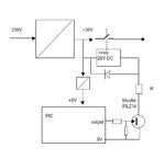
here is the principe ..
i will not do all the study for you ..

a standard 24V DC relay + a litle resitor or White led to absorbe the extra overvoltage ...
To define R , must know the coil resistor value of the relay

To define the relay.. give max value of Current wich will pass trought the contact


Principe.jpg
 
Hi,

i previously used a solod state relay.
Something similar to S202S02 from SHARP.

Works great

Klaus
 

Capture.JPG
This is what i have so far...its a circuit just to test the working of relay with a load equivalent of a 30V supply...what shoould the resistor value to be kept at gate and the bypassing resistor..??
 

Hi,
i previously used a solid state relay.
Something similar to S202S02 from SHARP...

he doesn't want to cut AC power supply..
Only 30V DC ..

maybe cut 30V AC .. but must power on the PIC from the 30V DC

- - - Updated - - -

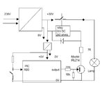
R1= 100 upt to 330 ohms
R2 = 10K ..up to 22K
R4 depend of your relais : coil resitance ..?
if R4=0 relay will over heat ...or add a zener diode (1W) of 5V instead of R4.

Your lamp will never bright on !

the contact relay must support the permanent current (and maxi current)
 

Capture.JPG
how will i get to know that relay is working?
i have kept R4 as 240 because relay coil resistance is 240 ohms.
what kind of configuration will i have to do if i want to test if this works? on simulation...
 

i have kept R4 as 240 because relay coil resistance is 240 ohms.

On a drawing, or with Proteus ISIS, the coil resistance value of a relay must not appears in serial with the relais ..
so it means need about 100mA to put Relais ON..
so R4 must be 56 ohms 1W 30 - (56*0.1) = 24.4V ( .. - U across Fet "ON")

What compiler do you use ?
MikroC
ASM ?
Other ?

FOSC interne ? or quartz ?

just recopie input to the output ..

Code:
//define RB0 as input
TRISB.B0=1;
//define RDO as output
TRISD.B0=0;
do
{
LATD0_bit= ! PORTB0_bit;
Delay_ms(100);
}
wile(1);


Principe.jpg
 
Last edited:

im using C18 compiler....and i have configured oscillator as HS oscillator in configuration bits in MPLAB IDE.......im not able to understand why my circuit is not working..Capture.JPG

Program:


Code C - [expand]
1
2
3
4
5
6
7
8
9
10
11
12
13
14
15
16
17
18
19
20
21
#include<p18f452.h>
#define sw PORTBbits.RB0
#define out PORTDbits.RD0
void main()
{
TRISBbits.TRISB0=1;
TRISDbits.TRISD0=0;
while(1)
{
    
    if(sw==1)
    {
      out=1;
     }  
    else
   
    out=0;
 
    
}
}


program is building with zero errors
 
Last edited by a moderator:

I am not clear about one thing...in your diagram..+30V line is connected to 5V supply...and the same line is connected to relay and diode...i didn't understand...could u please elaborate on that part?
 

Change

Code:
#define out PORTDbits.RD0

to

Code:
#define out LATDbits.LATD0

You have to use LATx registers for output ports in PIC18F.
 

I am not clear about one thing...in your diagram..+30V line is connected to 5V supply...and the same line is connected to relay and diode...i didn't understand...could u please elaborate on that part?

in previous post you said +5V pic is elaborated from 30V DC supply
so i put a square box wich represente your 5V adapter .. it could be a switching power supply...input=30V output=5V
You allways need to power ON the PIC , isn'it ?

if you want to use a linear Voltage regulator like 7805 .. you will get problems !
because 30V is over specif.. and need a Radiator to cool the device : Power dissipation : ( 30 - 5)* Icurrent
maybe you can use a 7815 -> 30V -> 15V then a 7805 15V-> 5V
Each regulator with a litle radiator

The 100mA for the relay will not pass through the regulators..

Your Lamp is connected between 0V and 0V , never will light on !
put the requiered voltage on one side ( +30V ?)

the diode is accross the coil to absorbe overvoltage ...
 
Last edited:

Use 30V DC to power the relay ,not VCC
i suppose Vcc is 5V for 18F

Code:
#include<p18f452.h>
#define sw PORTBbits.RB0
#define out [B]LATDbits.RD0[/B]
#define led LATDbits.RD1

void main()
{
TRISBbits.TRISB0=1;
TRISDbits.TRISD0=0;

while(1)
{
    
    if(sw==1)
    {
      out=1;
     }  
    else
       out=0;
  // test if programme is running 
   Led=1;
   delay_ms(500);
   Led=0;
    delay_ms(500);
    
}
}

Image1.jpg
 
finally its working :thumbsup:
Capture.JPG

there is a 470 ohm resistor with a LED...why is it required?

- - - Updated - - -

i mean to assk in the circuit which you sent..there is 470 ohm resistor with a LED at D1..why is it required?
 

Status
Not open for further replies.

Part and Inventory Search

Welcome to EDABoard.com

Sponsor

Back
Top